Active Cube Servo Drive Solutions
Power, control and green solutions
About us 3 Bonfiglioli, one name for a large international group It was back in 1956 that Clementino Bonfiglioli established in Bologna, Italy, the company that still bears his name. Now, some fifty years later, the same enthusiasm and dedication is driving Bonfiglioli to become the world’s top name in power transmission and control solutions.
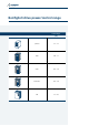
Bonfiglioli solutions wind industrial mobile photovoltaic
Innovative solutions for industrial field. Bonfiglioli Riduttori today is one of the top brands in the power transmission industry. The company’s success is the result of a business strategy that relies on three fundamental factors: know-how, innovation and quality. The complete range of Bonfiglioli brand gearmotors offers excellent technical characteristics and guarantees the highest performance.
Servo Drive Solutions
Advanced technologies for all industrial fields. The Bonfiglioli Active Cube series is designed to enable you to maximize the opportunities in machine automation. Extensive motor controls and functionality allow Active Cube to be used in the design of effective and easy automation solutions for a wide variety of industrial machinery and plants. Outstanding performance in terms of accuracy and response time put Active Cube in the high technology end of the Bonfiglioli Vectron drives range.
Bonfiglioli drive power/control range Power range [kW] Synthesis 0.2 ... 2.2 Agile 0.25 ... 11 Active 0.55 ... 132 Active Cube 0.25 ... 132 VCB 65 ...
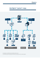
Bonfiglioli “system” range BN, M Induction motors BTD, BCR Synchronous servomotors Active Cube A C F VF, W LC, MP, TR Low backlash gearboxes HDP, HDO General purpose High accuracy High dynamics This catalogue concerns Active Cube series and Active Cube accessories. For information about the other products showed in above overview, please refer to relevant catalogues.
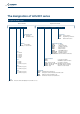
The designation of ACU201 series Designation ACU201 series Basic variants ACU 201 13 F Optional variants A MPSV EMSYS CMCAN User interface (blank) no user interface KP500 programming control unit KP232 RS232 serial interface Construction style A style with standard cooling EMI filter F internal filter (blank) no internal filter Communication modules (blank) no module CM-CAN CANopen interface CM-PDP Profibus DP interface CM-232 RS232 interface CM-485 RS485 interface CM-DEV DEVICENET interface
The designation of ACU401 series Designation ACU401 series Basic variants ACU 401 15 F A Optional variants MPSV EMSYS CMCAN Construction style A style with standard cooling EMI filter F internal filter (blank) no internal filter Size 1 01 0.25 kW 03 0.37 kW 05 0.55 kW 07 0.75 kW 09 1.1 kW 11 1.5 kW Size 2 12 1.85 kW 13 2.2 kW 15 3.0 kW 18 4.0 kW Size 3 19 5.5 kW 21 7.5 kW 22 9.2 kW Size 5 27 18.
Hardware Performance • High speed control loop and fast response time • Both “system drive” and “servo drive” • Optimized combination with Bonfiglioli BTD and BCR servomotor series Automation • Small dimensions and “power density” in all sizes • “Book shape” in smaller sizes for easy integration in automation cabinets • Integrated “safe Torque Off” function, according to EN954-1 cat.
Software Flexibility • Control both of asynchronous and synchronous actuators • Full set of operation modes, freely selectable: - Servo synchronous control with resolver feedback - Field oriented (vector) control with absolute encoder speed/sensor - Sensorless field oriented (vector) control • Flexible assignment of digital inputs and outputs to control software module variables • “Motor chopper” function to increase braking power without brake resistors • 4 independent data sets • Flying restart Automa
General technical data Environment Operating temperature • 0°C - 40°C (40°C - 55°C with derating) Standards CE conformity: • Low voltage directive 73/23/EEC and EN50178 / DIN VDE 0160 and EN61800 Environment class • Operation 3K3 (EN60721-3-3) • Relative humidity 15% ...
ACU201 - Technical data (from 0.25 to 3.0 kW) ACU201- 01 03 05 07 09 11 Size 1 (F, A) 13 15 Size 2 (F, A) Output, motor side Rated motor current output In A 1.6 2.5 3.0 4.0 5.5 7.0 9.5 12.5 Rated motor voltage output Un V Overload current Ipk A 3.2 5.0 4.5 6.0 7.3 10.5 14.3 16.2 Recommended rated motor power Pn kW 0.25 0.37 0.55 0.75 1.1 1.5 2.2 3.
ACU201 - Technical data (from 4.0 to 9.2 kW) ACU201- 18 19 21 22 Size 3 (- or F, A) Size 4 (-, A) Output, motor side Rated motor current output In A 18.0 22.0 32.0 35.0 Rated motor voltage output Un V Overload current Ipk A 26.2 30.3 44.5 51.5 Recommended rated motor power Pn kW 4.0 5.5 7.5 9.2 Switching frequency fc kHz From 2 to 6 Rated motor frequency fn Hz From 0 to 1000 Rated mains voltage U V 184 ... 264 Rated mains frequency f Hz 45 ...
ACU401 - Technical data (from 0.25 to 3.0 kW) ACU401- 01 03 05 07 09 11 12 Size 1 (F, A) 13 15 Size 2 (F, A) Output, motor side Rated motor current output In A 1.0 1.6 1.8 2.4 3.2 3.8 4.2 5.8 7.8 Rated motor voltage output Un V Overload current Ipk A 2.0 3.2 2.7 3.6 4.8 5.7 6.3 8.7 11.7 Recommended rated motor power Pn kW 0.25 0.37 0.55 0.75 1.1 1.5 1.85 2.2 3.
ACU401 - Technical data (from 4.0 to 15 kW) ACU401- 18 19 Size 2 (F, A) 21 22 Size 3 (- or F, A) 23 25 Size 4 (-, A) Output, motor side Rated motor current output In A 9.0 14.0 18.0 22.0 25.0 32.0 Rated motor voltage output Un V Overload current Ipk A 13.5 21.0 26.3 30.3 37.5 44.5 Recommended rated motor power Pn kW 4.0 5.5 7.5 9.2 11.0 15.0 Switching frequency fc kHz From 2 to 16 Rated motor frequency fn Hz From 0 to 1000 Rated mains voltage U V 320 ...
ACU401 - Technical data (from 18.5 to 30 kW) ACU401- 27 29 31 Size 5 (-, A) Output, motor side Rated motor current output In A 40.0 45.0 60.0 Rated motor voltage output Un V Overload current Ipk A 60.0 67.5 90.0 Recommended rated motor power Pn kW 18.5 22.0 30.0 Switching frequency fc kHz From 2 to 16 Rated motor frequency fn Hz From 0 to 1000 Rated mains voltage U V 320 ... 528 Rated mains frequency f Hz 45 ...
ACU401 - Technical data (from 37 to 65 kW) ACU401- 33 35 37 39 110.0 125.0 Size 6 (-, A) Output, motor side Rated motor current output In A 75.0 90.0 Rated motor voltage output Un V Overload current Ipk A 112.5 135.0 165.0 187.5 Recommended rated motor power Pn kW 37.0 45.0 55.0 65.0 Switching frequency fc kHz From 2 to 8 Rated motor frequency fn Hz From 0 to 1000 Rated mains voltage U V 320 ... 528 Rated mains frequency f Hz 45 ...
ACU401 - Technical data (from 75 to 132 kW) ACU401- 43 45 47 49 210.0 250.0 Size 7 (-, A) Output, motor side Rated motor current output In A 150.0 180.0 Rated motor voltage output Un V Overload current Ipk A 225.0 270.0 315.0 332.0 Recommended rated motor power Pn kW 75.0 90.0 110.0 132.0 Switching frequency fc kHz From 2 to 8 Rated motor frequency fn Hz From 0 to 1000 Rated mains voltage U V 320 ... 528 Rated mains frequency f Hz 45 ...
Inverter selection and dimensioning high technology “System drive” matched with asynchronous induction motors, and as a “Servo drive”, together with synchronous servomotors, two different criteria are proposed: Asynchronous induction motors (continuous load) Active Cube is driving traditional squirrel cage induction motors (e.g. Bonfiglioli M and BN series). Applications are usually featured by continuous torque supply for long time with occasional smooth overload needs.
Inverter selection and dimensioning and BCR series). Applications are usually featured by intermittent very high torque demand for short time. An example of typical torque profile is shown below. Torque Synchronous permanent magnets servomotors (intermittent load) Active cube is driving high performance synchronous PM servomotors (e.g. Bonfiglioli BTD Time In case of intermittent torque with high peaks, the dimensioning and selection of Active Cube, can be done through these steps: a.
Options modules Active Cube is designed to give the highest flexibility in drive hardware to suit every control requirement. Machine designers can select from an extensive range of possible expansion hardware modules that can be fitted directly into the 3 available slots on the standard Active Cube unit. Mounting and connection is fast and easy thanks to onboard fastening devices.
Options modules Option modules can be ordered either separately or together with ACU base unit, as an “extended” power package. The majority of Active Cube option modules can also be used in the Active series, thus allowing drives from both series to be easily used in the same automation system. Select from below the hardware module to customize Active Cube and build a unique drive which best fits to the needs of your application.
Control unit / KP500 The KP500 control unit is equipped with a Parameters Copy function that allows the user to upload parametric values from the inverter to a non-volatile memory installed in the KP500 device, allowing the same values to be subsequently downloaded to another inverter. The control unit makes it possible to set up the inverter for specific applications and allows the display of the service values of physical and electrical parameters.
Interface / KP-232 Serial interface KP232 can be used as an alternative to control unit KP500. This connection enables parameterisation, monitoring, setting management, inverter control and even commissioning from a PC or laptop computer.
RS232 / CM-232 serial communication The optional CM-232 communication card enables RS232 serial connection of the Active Cube inverter to an external control device or PC to ANSI standard EIA/TIA-232E and CCITT V.28. The standard defines the electrical and mechanical characteristics of serial connections between data terminating equipment (DTE) and data communication equipment (DCE). The serial interface, in the form of a DB9 plug, features DCE type pinouts.
RS485 / CM-485 serial communication The CM-485 communication module is designed for high speed data transmission over long distances in industrial applications. RS485 bus supports data exchange among 30 nodes in a bidirectional 2-wires system. The interface is based on a DB9 connector, following the standards for physical transmission of data ITU V.
RS485 / CM-485 serial and Modbus communication Modbus communication The communication module CM-485 allows to use the Modbus Communication profile to be used. The communication profile can be easily changed to Modbus with a parameter. Therefore a very inexpensive solution is available to integrate the Active Cube inverters in a Modbus Communication environment with the standard Active Cube devices and a standard module. There are two profiles available.
DP / CM-PDP V1 Profibus Communication Internal dipswitch to enable the 220 Ω terminating burden resistor incorporated in the module Cable lenght Max Baud rate up to 1200m 93.75 up to 1000m 187.5 up to 400m 500 up to 200m 1500 up to 100m 12000 Profibus DP interface fulfils fieldbus standard DIN 19245.
CANopen / CM-CAN communication The CM-CAN communication option with controller area network interface, complies with ISO/DIS 11898 transmission standard. The pinout of connector DB9 is based on the “CAN in Automation e.V.” specification, which allows the connection of up to 127 nodes in the network. The network node addresses are assigned via software. The endburden resistor is activated by means of a DIP switch on the module.
Devicenet / CM-DEV communication DeviceNet interface CM-DEV fulfils ODVA/CIP specification. It supports 2 types of connection: explicit message and I/O message. For I/O data exchange the following CIP defined output assemblies and input assemblies for AC drives are available: output assemblies 20, 21, 22, 24, input assemblies 70, 71, 72, 74. In addition, the vendor specific output assembly 100 and input assembly 101 are available.
EtherCAT® / CM-EtherCAT® communication The EtherCAT® communication module CM-EtherCAT® is compliant with the standard of EtherCAT® Technology Group (ETG). SDO and PDO objects are managed. Standard DS402 ”drive motion control” modes are supported: Profile position mode, Velocity mode, Profile velocity mode, Homing, Interpolated mode. Access and control of all parameters of frequency inverter is possible from external control unit (e.g. PLC) which is compatible with EtherCAT® standard.
Profinet / CM-ProfiNet communication Profinet interface CM-ProfiNet allows Active Cube to communicate effectively with Profinet networks. 2 configurations are supported: non-motion configuration (based on Active Cube speed control configurations) and motion control configurations (via Motion Control Interface MCI). Several modes of operation are implemented in motion control configuration : Profile position mode, Velocity mode, Profile velocity mode, Homing and the proprietary Table Travel record mode.
Ethernet VA BUS TCP / CM-VABus/TCP communication The CM-VABus/TCP modules supports an Ethernet TCP/IP connection. 2 versions are available: CM-VABus/TCP version has one active RJ connector, while CCMVABus/TCP 2P version has two active RJ connectors and implements switch function for daisy chaining of multiple inverters.
System bus / EM-SYS module The “System Bus” of Active Cube inverters is a proprietary communication bus, based on CANopen protocol that allows fast exchange of data between the inverters and access, by a system bus master, to the parameters of all devices connected on the network. The system bus nodes (max. 64) are connected by a two-wire line. The Bus termination (at either first or last node) can be activated via DIP switches of the EM-SYS module.
Input-output module / EM-IO-01 The EM-IO-01 expansion module extends the number of the standard inputs and outputs provided on the ACT inverter for connection of various applications. Analog inputs and outputs can be available also with bipolar signals and must therefore be configured with inverter parameters. The supplementary digital inputs provided on the expansion module are electrically equivalent to the standard inputs.
Input-output module / EM-IO-02 Like EM-IO-01, the EM-IO-02 expansion module extends the standard inputs and outputs featured on ACT frequency inverters. The EM-IO-02 module has a slightly modified layout compared to the -01 version, featuring an input for a PTC thermal probe in place of one of the module relay outputs. The functions of all the other terminals are same as in EM-IO-01.
Input-output module / EM-IO-03 The EM-IO-03 expansion module is another variant for the extension of I/O facilities of ACTIVE frequency inverters. Terminal board X410A 1 2 3 4 5 6 7 +20V / 180mA GND 20V EM-S2OUTA EM-S2IND EM-S3IND EM-S1OUTD EM-S1OUTD Terminal board X410B PTC 10Vref θ 1 2 3 4 5 6 7 PTC GND-PTC EM-S1INA EM-S1OUTA CAN-Low CAN-High GND 10V Terminal Function X410A.1 20 V DC power supply output (180 mA) X410A.2 20 V power supply GND X410A.
Input-output module / EM-IO-04 The EM-IO-04 expansion module is another variant for the extension of I/O facilities of ACTIVE frequency inverters. Terminal board X410A 1 2 3 4 5 6 7 +20 V GND 20 V EM-S2IND +20 V GND 20 V EM-S3IND +20 V Terminal board X410B SYS 1 2 3 4 5 6 7 EM-MPTC / EM-KTY EM-S1IOD GND 20 V CAN-Low CAN-High CAN GND Location of EM-IO-04 module on the frequency inverter Terminal Function X410A.1 Voltage output 20 V X410A.2 Earth / GND 20 V X410A.
Speed sensor module / EM-ENC-01 The EM-ENC-01 expansion module extends the number of speed sensor inputs of terminal board of the frequency inverter, and also increases the number of configurable pulse outputs with encoder repetition output with encoder repetition output. EM-ENC-01 is able to acquire both TTL and HTL incremental speed sensors according to standard EIA RS422 (line driver) with 5-volt logic.
Speed sensor module / EM-ENC-02 The EM-ENC-02 speed sensor module extends the standard terminal board of the inverter, providing an interface for line driver encoders with relative DC + 5 V power supply. The same module is equipped also with a DC 0 ... 20 mA and +/- 20 mA analog input and a DC + 20 mA analog output, together with an input for a PTC thermal probe and a digital port configurable as an input or output. Also this module is equipped with a Systembus port.
Speed sensor module / EM-ENC-03 The EM-ENC-03 extends the standard terminal board of the inverter, providing an interface for line driver speed sensors. Also this module is equipped with a Systembus port. ENCODER LineDriver Terminal board X410A 1 2 3 4 5 6 7 Terminal Function X410A.1 Channel A speed sensor input A A B B X410A.2 Channel A speed sensor input X410A.3 Channel B speed sensor input X410A.4 Channel B speed sensor input X410A.5 - GND X410A.6 GND X410A.
Speed sensor module / EM-ENC-04 The EM-ENC-04 speed sensor module extends the standard terminal board of the inverter, providing an interface for line driver speed sensors with Z channel. This module is able to manage TTL, HTL, or push-pull incremental speed sensors to standard EIA RS422 (line driver). The EM-ENC-04 speed encoder module is equipped with 6 control terminals for A, A, B, B direction signals and Z and Z zero signals transmitted by the speed sensor.
Speed sensor module / EM-ENC-05 The EM-ENC-05 speed sensor module extends the standard terminal board of the inverter, providing an interface for line driver speed sensors with Z channel. This module is able to manage TTL, HTL, or push-pull incremental speed sensors to standard EIA RS422 (line driver). The EM-ENC05 speed encoder module is equipped with 6 control terminals for A, A, B, B direction signals and Z and Z zero signals transmitted by the speed sensor.
Resolver Module / EM-RES-01 The EM-RES-01 angular position transducer module extends the standard functions of the frequency inverter by providing a supplementary input for a resolver (electromechanical absolute speed sensor). Resolver gives the instantaneous motor shaft position value even at standstill, and its angular position within a revolution.
Resolver Module / EM-RES-02 EM-RES-02 angular position transducer module extends the standard functions of the frequency inverter by providing a supplementary input for a resolver. This module shares all the features of EM-RES-01 except for the emulation of the encoder zero signal, which in this case replaces the Systembus port.
Resolver Module / EM-RES-03 EM-RES-03 resolver module extends the standard functions of Active Cube servo inverter providing a supplementary input for resolver. It is designed specifically for BTD/BCR synchronous servomotors resolver feedback acquisition. EM-RES-03 is equipped with DB9 connector, that allows fast and easy connection to Bonfiglioli synchronous servomotors, when using BTD/BCR power and control cables.
Encoder Module / EM-ABS-01 The expansion module EM-ABS-01 extends the ability of Active Cube inverter to acquire different absolute encoder feedbacks. The following encoder standards can be connected to the drive via EM-ABS-01: • SinCos (optionally with commutation tracks) • Endat 2.
Engineering software VPlus is a PC Windows-based engineering software tool that guides industrial automation designers through the steps towards the definition of the optimal configuration of Active Cube drives. Communication between VPlus and the drive is based on standard serial communication either through KP232, CM232, CM-485 or CM-VATCP interface.
Function highlights Active Cube control levels Active Cube has by far the widest application potential of all Bonfiglioli drive offer, thanks to its extremely rich set of functionalities, combined with flexible hardware structure and significant power range extension.
Function highlights Machine control level Within each Motor control mode, a range of “machine” control functions, belonging to Machine control level, is available.
Safe torque off (STO) The safety function “Safe Torque Off” (STO) with the safety integrity level SIL 2 (see DIN EN 61508 and DIN IEC 61800-5-2) is implemented into standard Active Cube inverter range. The drive feature helps overall automation system to achieve “Safe Stop“ category 3, according to DIN EN 954-1. Thanks to STO function, energy supply from frequency inverter to motor is safely disabled.
Logic functions 1 2 3 4 5 6 7 8 9 10 11 12 ... I1 O1 I2 ? 1 I3 I4 O2 Sophisticated control routines design is within range with new logic functions. Software developers will be able to adjust drive controls fitting automation requirements, simply combining the 16 inputs with the 32 function blocks available and achieving results in the 16 output latches. Following features are implemented: Input buffer for up to 16 signals e.g.
Motion functions Motion blocks The “elemental software unit” of motion control in Active Cube is the “Motion Block”.
Motion functions Homing A comprehensive set of homing functions, according to CANOpen DSP 4.02 standard is available in Active Cube. 36 different homing modes can be used to answer to the motion requirements of a wide range of machines. Homing search can be triggered by either digital input (e.g. hardware limit switches), or control word (if Fieldbus is used), or as an automatic procedure before first positioning sequence. 8 7 7 10 9 10 8 7 9 9 8 10 North Marker Home Switch Pos.
Servo package When using Active Cube in servo applications, you can get the best out of the drive when applied together with Bonfiglioli servomotors. Active Cube and Bonfiglioli servomotors were, in fact, designed to exploit at best reciprocal synergies thus forming a servo “package”, able to provide significant advantages to users both in terms of enhanced performance and in terms of reduced setup time.
Bonfiglioli servomotors range Bonfiglioli servomotors offer includes 2 series of permanent magnet synchronous servomotors, BTD (Bonfiglioli Torque Density) and BCR (Bonfiglioli Classic Range) featured by different speed and torque ranges, achieved through different construction technologies. BTD and BCR series are split into many frame sizes, each of them grouping together devices with same flange dimensions and different motor lengths able to supply different torque ratings within one frame size.
ACU 230V vw BTD 230V BTD... 2-0026 2-0053 2-0074 2-0095 3-0095 3-0190 3-0325 3-0420 Mn 0.25 0.42 0.45 0.65 Mmax 0.74 0.84 0.89 1.29 Mn 0.47 0.69 0.72 0.92 1.09 Mmax 1.35 1.43 1.45 2.07 2.17 Mn 0.69 0.86 0.92 1.63 2.63 Mmax 2.01 2.04 2.91 3.05 3.94 Mn 0.69 0.86 0.92 1.63 3.02 3.24 Mmax 2.67 2.71 3.49 4.07 4.53 5.25 Active Cube drive ACU201-01 ACU201-03 ACU201-05 ACU201-07 ACU201-09 ACU201-11 ACU201-13 ACU201-15 Mn 0.86 1.63 3.02 3.
4-0410 4-0630 4-0860 5-1160 5-1490 3.42 4.83 5.38 7.18 7.25 8.06 3.42 4.83 6.37 9.77 9.87 10.98 3.42 4.83 11.14 5-1870 5-2730 6.37 8.38 9.27 11.25 12.52 10.93 12.08 4.83 6.37 8.85 11.56 18.15 20.19 17.63 19.50 6.37 8.85 11.56 14.75 18.54 23.27 20.32 22.46 20.31 25.53 8.85 11.56 15.01 21.40 29.84 32.99 29.83 37.50 8.85 11.56 15.01 21.40 34.53 38.18 34.52 43.39 2.73 4.10 3.42 4.
ACU 400V vw BTD 400V BTD... 2-0026 2-0053 2-0074 2-0095 3-0095 3-0190 Mn 0.42 0.48 0.69 0.73 0.72 1.14 Mmax 1.05 1.45 3-0325 3-0420 2.44 2.52 Active Cube drive ACU401-01 ACU401-03 ACU401-05 ACU401-07 ACU401-09 ACU401-11 ACU401-12 ACU401-13 ACU401-15 ACU401-18 ACU401-19 ACU401-21 ACU401-22 ACU401-23 ACU401-25 1.54 1.45 1.44 2.29 Mn 0.69 0.86 0.92 1.67 Mmax 2.47 2.32 2.30 3.66 Mn 0.69 0.86 0.92 1.67 Mmax 2.08 1.96 1.94 3.09 3.66 3.78 Mn 0.
4-0410 4-0630 4-0860 5-1160 5-1490 5-1870 10.73 10.26 5-2730 2.89 4.34 3.38 4.23 5.79 6.34 3.38 4.75 6.87 7.53 3.38 4.75 5.64 7.60 8.32 8.47 3.38 4.75 6.45 10.49 11.49 11.69 4.75 6.45 8.70 15.45 15.72 13.05 4.75 6.45 8.81 17.83 18.14 15.06 16.09 15.39 8.81 11.44 14.94 20.12 23.42 25.03 23.95 30.17 8.81 11.44 14.94 21.41 29.33 31.35 29.99 37.79 8.81 11.44 14.94 21.41 33.80 36.12 34.55 43.54 11.44 14.94 21.41 44.70 42.76 53.88 14.
ACU 230V vw BCR 230V BCR... 2-0020 2-0040 2-0060 2-0080 3-0065 3-0130 3-0250 3-0300 4-0100 4-0260 4-0530 4-0750 Active Cube drive ACU201-01 ACU201-03 ACU201-05 ACU201-07 ACU201-09 ACU201-11 ACU201-13 ACU201-15 ACU201-18 ACU201-19 ACU201-21 Mn 0.20 0.38 0.49 0.51 0.47 Mmax 0.68 0.86 0.98 1.03 0.94 Mn 0.38 0.58 0.75 0.62 0.87 0.87 Mmax 1.38 1.56 1.64 1.51 1.73 1.75 Mn 0.58 0.75 0.62 1.08 1.88 1.88 0.98 2.52 Mmax 2.20 2.31 2.12 2.44 2.81 2.81 2.46 3.
5-0660 5-1050 5-1350 5-1700 5-2200 6-1350 6-1900 6-2200 6-2900 7-2700 7-3200 7-4000 4.63 6.26 5.83 9.00 5.83 7.44 12.26 11.21 5.83 9.01 9.70 11.55 11.56 13.97 12.77 12.65 15.06 15.07 5.83 9.01 11.25 14.78 15.47 13.50 14.87 22.54 20.61 20.41 24.30 22.60 24.32 21.73 9.01 11.25 14.78 17.36 13.50 17.60 18.91 20.38 21.06 21.46 20.00 23.74 23.51 27.99 26.04 28.02 25.03 26.04 28.07 29.01 29.56 27.55 9.01 11.25 14.78 17.36 13.50 17.60 19.
ACU 400V vw BCR 400V BCR... 2-002 2-0040 2-0060 2-0080 3-0065 3-0130 3-0250 3-0300 4-0100 4-0260 4-0530 4-0750 5-0660 Active Cube drive ACU401-01 ACU401-03 ACU401-05 ACU401-07 ACU401-09 ACU401-11 ACU401-12 ACU401-13 ACU401-15 ACU401-18 ACU401-19 ACU401-21 ACU401-22 ACU401-23 ACU401-25 ACU401-27 ACU401-29 ACU401-31 ACU401-33 Mn 0.20 0.38 0.58 0.76 0.62 0.91 0.94 Mmax 0.85 1.48 1.64 1.76 1.65 1.82 1.89 Mn 0.58 0.76 0.62 1.13 0.99 Mmax 2.55 2.81 2.63 2.
5-1050 5-1350 5-1700 5-2200 6-1350 6-1900 6-2200 6-2900 7-2700 7-3200 7-4000 8-0400 8-0680 8-0930 8-1150 8.34 12.51 9.06 12.84 16.83 19.26 9.06 10.85 19.42 16.27 9.06 11.45 30.21 25.31 11.45 13.42 15.47 13.50 12.39 13.56 15.19 20.13 23.20 22.23 18.59 20.34 14.91 18.05 13.50 17.62 19.74 23.60 22.78 23.58 22.67 25.69 31.32 36.09 34.57 28.91 31.64 35.41 35.44 35.37 34.01 38.53 14.91 18.05 13.50 17.62 19.74 24.78 22.78 25.26 28.99 32.66 31.70 39.22 45.
Mounting A wide range of mechanical accessories is available for Active Cube Series frequency converters, to make installation extremely easy in all sorts of applications. In standard mountings the unit can be installed directly on the mounting plate or through-thewall. A vibration-proof mounting variant and a standard DIN bar mounting variant are also available.
Size 1 Inverter Bonfiglioli ACU 201-01 … ACU 201-09 ACU 401-01 … ACU 401-11 Mounting Description MPSV1 Thru-type assembly MNVIB1 Antivibration assembly MDIN1 DIN rail assembly B Standard assembly A B A MPSV1 MNVIB1 MDIN1 A A B B
Size 2 Inverter Bonfiglioli ACU 201-11 … ACU 201-15 ACU 401-12 … ACU 401-18 Mounting Description MPSV2 Thru-type assembly MNVIB2 Antivibration assembly MDIN2 DIN rail assembly Standard assembly MPSV2 A A B B MNVIB2 A A B B MDIN2 A A B B
Size 3 Inverter Bonfiglioli Mounting Description ACU 201-18 … ACU 201-19 ACU 401-19 … ACU 401-22 MPSV3 Thru-type assembly MNVIB3 Antivibration assembly Standard assembly A A B B MPSV3 A A B B MNVIB3 A A B B
Size 4 Inverter Bonfiglioli Mounting Description ACU 201-21 … ACU 201-22 ACU 401-23 … ACU 401-25 MPSV4 Thru-type assembly MNVIB4 Antivibration assembly Standard assembly A A B A B B MPSV4 MNVIB4 A B
Size 5 Inverter Bonfiglioli ACU 401-27 … ACU 401-31 Standard assembly Mounting Description MPSV5 Thru-type assembly MNVIB5 Antivibration assembly A A B A B B MPSV5 MNVIB5 B A
Size 6 Inverter Bonfiglioli ACU 401-33 … ACU 401-39 Standard assembly Mounting Description MPSV6 Thru-type assembly MNVIB6 Antivibration assembly A A B B MPSV6 MNVIB6 A A B B
Size 7 Inverter Bonfiglioli Mounting Description ACU 401-43 ...
Input filter Why an input filter? An Input Filter is a filtration device to be installed up-line from the frequency inverter and down-line from the power feeding contactor. The AC/DC rectifier at the inverter input generates harmonic disturbance on the absorbed current and returns disturbance generated by switching components towards the mains. This harmonic current causes voltage distortions on the mains resulting in electromagnetic interference phenomena.
Line choke The simplest way of reducing high harmonic components and hence reactive power is connecting a choke in series on the mains side of the inverter. Depending on the system, reactive power consumption can be reduced by approximately 20% of the figure without line choke. The line choke increases inductance towards the mains. Mains feed line choke can be regarded as sufficient if short-circuit power is from 20 to 40 times higher than the inverter nominal output.
Line choke Dimensions c PE d n1 n2 b a Technical data Bonfiglioli frequency inverter - Line choke combination, 1x230V~ Bonfiglioli inverter Bonfiglioli choke Nominal current Power dissipation [A] [W] LCVS006 6 8.0 ACU 201-07 LCVS008 8 8.0 ACU 201-09 LCVS010 10 10.0 ACU 201-11 LCVS015 15 12.0 ACU 201-13 LCVS018 18 15.
Line choke Dimensions LCVT004 ... LCVT025 LCVT034 ... LCVT250 U1 U2 V1 V2 W1 W2 PE c c U1 U2 V1 V2 W1 W2 d n2 a n1 b Technical data Bonfiglioli inverter n2 n1 a b Bonfiglioli frequency inverter – Line choke combination, 3x230V~ Bonfiglioli choke Nominal current Choke Power dissipation [A] [mH] [W] LCVT004 4 7.32 20 ACU 201-09 LCVT006 6 4.88 25 ACU 201-11 LCVT008 8 3.66 30 ACU 201-13 LCVT010 10 2.93 30 ACU 201-15 LCVT015 15 1.95 45 ACU 201-18 LCVT018 18 1.
Line choke Technical data Bonfiglioli inverter Bonfiglioli frequency inverter – Line choke combination, 3x400V~ Bonfiglioli choke Nominal current Choke Power dissipation [A] [mH] [W] 4 7.32 20 ACU 401-01 ACU 401-03 ACU 401-05 ACU 401-07 LCVT004 ACU 401-09 ACU 401-11 ACU 401-12 ACU 401-13 LCVT006 6 4.88 25 ACU 401-15 LCVT008 8 3.66 30 ACU 401-18 LCVT010 10 2.93 30 ACU 401-19 LCVT015 15 1.95 45 ACU 401-21 LCVT018 18 1.63 70 ACU 401-22 LCVT025 25 1.
EMI filters Because of their intrinsic characteristics, all frequency inverters often generate undesired high frequency voltages generally referred to as “interference”. Mains filters are installed to reduce this interference. Within the European Union reference standard EN EN61800-3 defines the thresholds for electromagnetic interference for different classes of equipment. Active Cube series frequency inverters up to size 9.
Backplate EMI filters Note These mains filters are installed between the line choke and the frequency inverter. The frequency inverter installed on the EMI filter must be connected to the metal baseplate with a short, large section earth connection. Overload capacity is 1.5 times rated current for 1 minute, every 30 minutes. Mains voltage 3 x 480V~ maximum +10% Nominal current 8A ... 40A Frequency 50/60 Hz Operating and storage temperature -25 °C ... +100 °C (climate class acc.
Backplate EMI filters Dimensions FTV007B A A F C E D M G K B L1 L2 J H A EMI filter A B C D E F G H J K L1 340±0.3 315 5.5 L2 M [mm] FTV007B 351 62 45 200±10 160±10 33 45±0.2 240±0.2 280±0.2 7 Dimensions FTV018B - FTV040B A U2 V2 W2 A D L1 G M6 L2 H A U1 V1 W1 M6 K C B EMI filter A B C D G H K L1 L2 [mm] FTV018B 315 100 65 300 35 300 6.3 76 270 FTV040B 315 125 65 300 60 300 6.
Book type EMI filters Mains voltage 3 x 480 VAC Maximum length of motor cables: ACU 401-01 to -15: 25 m class B ACU 401-18 to -25: 50 m class B ACU 401-27 to -39: 10 m class B, 100 m class A group 1 ACU 401-43 to -49: 10 m class B, 100 m class A group 1 Rated current 7 A … 130 A Frequency up to 60 Hz Note Overload capacity is 4 times rated current at switchon; 1.5 times rated current for 1 minute, once per hour. Operating and storage temperature -25 °C ... +80 °C (climate class acc.
Book type EMI filters Dimensions FTV007A ... FTV180A I L C D H J K A G F B E EMI filter A B C D E F G H I J K L FTV007A 190 40 70 160 180 20 FTV016A 250 45 70 220 4.5 1 22 235 25 5.4 1 22 M5 20 29.5 M5 22.5 FTV030A 270 50 85 240 255 30 5.4 1 29.5 25 M5 25 FTV055A 250 85 90 220 235 60 5.4 39.5 1 39 M6 42.5 FTV075A 270 80 135 240 255 60 26.5 6.5 1.5 39 M6 40 FTV100A 270 90 150 240 255 70.5 65 6.5 1.
Braking resistors When speed of an inverter-controlled ac motor is reduced, the motor acts as a generator, feeding back energy to the frequency inverter. As a result, voltage in the intermediate circuit of the inverter increases. When a specific threshold is exceeded, the energy must flow to an external braking system in order to avoid drive failures. Braking resistors are designed to absorb such energy and to dissipate it into heating.
Braking resistors Active Cube drive combination chart These charts show recommended combinations for each model in the Active Cube range, and specify the corresponding duty cycles on the basis of rated drive Active Cube Series Bonfiglioli braking resistor kW power. Contact your nearest Bonfiglioli Drive Centre for particularly heavy-duty braking applications or if you need to customise a product. Resistance Continuous rated power Duty cycle at the drive’s rated power Ohm [W] ACU 201-01 0.
Added value
We want to share the value of our work with you. The development of effective, tailored solutions for a wide range of applications is a fundamental aspect of our work. We succeed so well because we co-operate closely with our customers, listen to their requests and work with them to improve our own performance.
Branches and facilities Our branches Bonfiglioli Canada Bonfiglioli USA Bonfiglioli France Bonfiglioli Brasil Bonfiglioli United Kingdom Tecnotrans Bonfiglioli Bonfiglioli Deutschland Bonfiglioli South Africa Bonfiglioli Österreich Bonfiglioli India Bonfiglioli Italia Bonfiglioli South East Asia Bonfiglioli Türkiye Bonfiglioli Vietnam Bonfiglioli Australia Bonfiglioli China Bonfiglioli New Zealand Our production facilities ITA1 Bonfiglioli Riduttori S.p.A.
Bonfiglioli is your partner worldwide for power transmission and motion control. Customer satisfaction has always been one of Bonfiglioli’s key values. It is pursued around the world, and in a wide range of contexts, by a network of subsidiaries located in 17 countries and on 5 continents. Each subsidiary provides rapid and efficient pre-sales and after-sales service, and can guarantee prompt deliveries from local assembly plant and warehouses.
Bonfiglioli worldwide network. Bonfiglioli Australia 2, Cox Place Glendenning NSW 2761 Locked Bag 1000 Plumpton NSW 2761 Tel. (+ 61) 2 8811 8000 - Fax (+ 61) 2 9675 6605 www.bonfiglioli.com.au - sales@bonfiglioli.com.au Bonfiglioli New Zealand 88 Hastie Avenue, Mangere Bridge, Auckland 2022, New Zealand - PO Box 11795, Ellerslie Tel. (+64) 09 634 6441 - Fax (+64) 09 634 6445 npollington@bonfiglioli.com.
Bonfiglioli has been designing and developing innovative and reliable power transmission and control solutions for industry, mobile machinery and renewable energy applications since 1956. Bonfiglioli Riduttori S.p.A. Via Giovanni XXIII, 7/A 40012 Lippo di Calderara di Reno Bologna (Italy) tel: +39 051 647 3111 fax: +39 051 647 3126 bonfiglioli@bonfiglioli.com www.bonfiglioli.