
Technical data


46
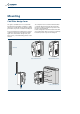
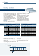
Braking resistors
Since each resistor has a lower continuous rated
power value than the corresponding drive, it is
important to respect the specified dissipation cycle.
Though the component will heat up, this cycle permits
adequate cooling.
The purpose of the reference cycle is to inform users
that over a period of 120 seconds, braking time must
not exceed 1.2 d
R
seconds, or the resistor will overheat.
The reference cycle is therefore a limit cycle and must
not be exceeded.
Given an application with a user-defined period T,
during which the drive’s full rated power is deviated
to the resistor, braking time must not exceed the
value of T
Fmax
calculated on the basis of the reference
cycle.
Braking cycle
Energy dissipated
to resistor
P rated
drive
T
T
Fmax
= T ≤ 1.2 δ
R
δ
R
100
T
F
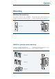
Regenerative mode
When an inverter-controlled electric motor is braking,
it becomes regenerative and returns electrical energy
to the drive.
This causes voltage in the drive’s intermediate circuit
to rise to a value at which it becomes necessary to
dispose of excess energy through a recovery system or
through external dissipative components.
Agile drives support both methods of regeneration
energy management and provide a DC-bus power
connection to other drives capable of using the excess
energy, and a connection to a braking resistor for the
thermal dissipation of energy.
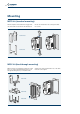
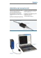
Braking Resistor
All Agile drives have a built-in braking chopper for
use with a range of Bonfiglioli braking resistors,
selected to suit the duty cycle of the application.
BR Series braking resistors are safe and compact, offer
an index of protection of IP20 and above, are suitable
for panel mounting and feature integrated thermal
protection.
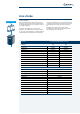
BR resistors can be used with all Bonfiglioli drives,
from the AGL Series to the ACT, ACU and VCB Series.
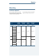
Each resistors is identified by a power rating and
a resistance value, which form the criteria for
combination with different drive ratings.
To help identify the most suitable braking resistors
for different drives and applications, the following
table suggests pairings that allow drives to dissipate
their full rated power to the resistor for a limited by
cyclically repeatable time.
Inverter
Recommended
resistor
Reference cycle*
AGL402 kW Type %
-02 0.25 BR 213/300 85
-03 0.37 BR 213/300 58
-05 0.55 BR 213/300 39
-07 0.75 BR 213/300 28
-09 1.1 BR 213/300 19
-11 1.5 BR 213/300 14
-13 2.2 BR 213/300 10
-15 3.0 BR 471/136 16
-18 4.0 BR 471/136 12
-19 5.5 BR 1330/48 24
-21 7.5 BR 1330/48 18
-22 9.2 BR 1330/48 14
-23 11 BR 1330/48 12
* referred to a period of 120 seconds
Inverter
Recommended
resistor
Reference cycle*
AGL202 kW (1ph) kW (3ph) Type % (1ph) % (3ph)
-02 0.12 0.25 BR 160/100 100 64
-03 0.18 0.37 BR 160/100 89 43
-05 0.25 0.55 BR 160/100 64 29
-07 0.37 0.75 BR 160/100 43 21
-09 0.55 1.1 BR 160/100 29 15
-11 0.75 1.5 BR 432/37 57 29
-13 1.1 2.2 BR 432/37 39 20
-15 1.5 3.0 BR 432/37 29 14
-18 2.2 4.0 BR 432/37 20 11
-19 3.0 5.5 BR 667/24 22 12
-21
3.0 - BR 667/24 22 -
- 7.5 2x BR 423/37* - 11
* 2x BR 423/37 parallel