
Technical data


23
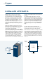
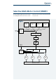
A drive with a PLC built in
The OS scans input and output buffers, samples
input signals and executes output signals before it
indexes the sequence of active modules.
As in any control panel PLC, cycle management
is entrusted to the operating system and is
independent of all other processes managed by
the CPU.
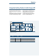
The program is therefore deterministic and scan time
proportional to the number of active function blocks.
In any automation process, the cycle period can be
calculated by summing the 1-ms delays introduced
by each function block.
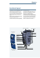
Agile PLC functions can be programmed using
VPlus software, which graphically displays the
program to which the drive’s memory corresponds
in real time.
VPlus software also provides a page that can be
used to load graphic function blocks and link them
together to create complex logic networks for use
by the drive.
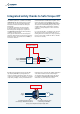
The Agile PLC supports and processes all the
variables used by the drive software, including I/O
variables, strings exchanged over the field bus and
numeric motor control values. The PLC is therefore
perfectly able to exchange signals with external
devices like sensors, actuators, inverters, PLCs, PC’s,
etc.) as well as with the drive itself.
External
devices
Motor
control
routine
Agile
I/O
PLC area
Field bus
External
devices
Input Latches & Output Latches
Active function blocks
Inactive
function blocks
Instructions
Function
block 1
I = 1
Function
block 2
I = 2
Function
block 3
I = 3 I = 4
P1343 = 0
Write
output buffer
Update
input buffer
24xx
25xx
20xx
23xx
1. ms
5. ms
...
2. ms
6. ms
...
3. ms
7. ms
...
4. ms
8. ms
...
(Return)
CYCLE