Agile Advanced Standard Drive
Power, control and green solutions
About us 3 Bonfiglioli, one name for a large international group. It was back in 1956 that Clementino Bonfiglioli established in Bologna, Italy, the company that still bears his name. Now, some fifty years later, the same enthusiasm and dedication is driving Bonfiglioli to become the world’s top name in power transmission and control solutions.
Bonfiglioli solutions wind industrial mobile photovoltaic
Innovative solutions for industrial field. Bonfiglioli Riduttori today is one of the top brands in the power transmission industry. The company’s success is the result of a business strategy that relies on three fundamental factors: know-how, innovation and quality. The complete range of Bonfiglioli brand gearmotors offers excellent technical characteristics and guarantees the highest performance.
Advanced Standard Drive
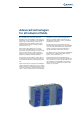
Advanced technologies for all industrial fields. The new Agile Series of inverter drives from Bonfiglioli sets new standards in technology for a broad range of users. Agile drives are particularly suited to the food & beverage, textile, wood, packaging and ceramic industries, where they can be used with a variety of medium complex automation processes. Agile inverter drives implement a sensorless vector control algorithm that offers excellent performance in speed and torque control.
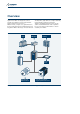
Overview Agile inverter drives are designed to control asynchronous induction motors and permanent magnet synchronous servomotors. With their sleek, compact cases, Agile drives have been specially developed for maximum functional integration. With a wide range of hi-tech functions Line choke already built in, Agile drives are complete and fully functional drives despite their small size.
Areas of application Agile inverter drives can be used in all areas of industry, but are particularly suited to the following applications: Food & Beverage Vertical stocking system Textile Wood Packaging Ceramics
Agile 402 series Selection guide To order an Agile inverter drive, you need to specify the designation string corresponding to it. This comprises a series of fields that define exactly and uniquely what drive you need for your particular application. The first five fields identify the drive and its basic variants. These fields must be mandatorily compiled in your order. You cannot leave any of these fields blank. The next four fields on the other hand define optional configurations for your drive.
Agile 202 series Designation Basic variants AGL 202 13 1 Optional variants F A MPSV CMPDP Design version A standard cooling (default) C Cold Plate 3ph 230V Size 1 02 0.25 kW 03 0.37 kW 05 0.55 kW 07 0.75 kW 09 1.1 kW 11 1.5 kW 13 2.2 kW 1ph 230V Size 1 02 0.12 kW 03 0.18 kW 05 0.25 kW 07 0.37 kW 09 0.55 kW 11 0.75 kW 13 1.1 kW Size 2 15 3.0 kW 18 4.0 kW Size 2 15 1.5 kW 18 2.2 kW Series AGL 202 inverter 1ph/3ph 200-240 V ± 10% Size 3 19 5.5 kW 21 7.
Basic offer Agile 402 series Inverter Power supply Power Filter [V] [kW] AGL402-02 1 F A 3ph 400 0.25 Integrated AGL402-03 1 F A 3ph 400 0.37 Integrated AGL402-05 1 F A 3ph 400 0.55 Integrated AGL402-07 1 F A 3ph 400 0.75 Integrated AGL402-09 1 F A 3ph 400 1.1 Integrated AGL402-11 1 F A 3ph 400 1.5 Integrated AGL402-13 1 F A 3ph 400 2.2 Integrated AGL402-15 2 F A 3ph 400 3.0 Integrated Dimensions [HxDxW] 200 x 170 x 60 200 x 196 x 80 AGL402-18 2 F A 3ph 400 4.
Basic offer Agile 202 series Inverter AGL202-02 1 F A AGL202-03 1 F A AGL202-05 1 F A AGL202-07 1 F A AGL202-09 1 F A AGL202-11 1 F A AGL202-13 1 F A AGL202-15 2 F A AGL202-18 2 F A AGL202-19 3 F A AGL202-21 3 F A Power supply Power [V] [kW] 3ph 230 0.25 1ph 230 0.12 3ph 230 0.37 1ph 230 0.18 3ph 230 0.55 1ph 230 0.25 3ph 230 0.75 1ph 230 0.37 3ph 230 1.1 1ph 230 0.55 3ph 230 1.5 1ph 230 0.75 3ph 230 2.2 1ph 230 1.1 3ph 230 3.0 1ph 230 1.5 3ph 230 4.
Innovation at the service of people Agile inverter drives help bridge the gap between user and process by providing software and hardware functions that simplify the management of complete systems. USER PROCESS Agile inverter process drives provide accurate sensorless vector control of asynchronous induction motors and permanent magnet synchronous motors, and also help manage the complete automation system by contributing to energy saving, safety, maintenance and logic control.
Innovation at the service of people Rapidity It only takes a few minutes to install and set up an Agile drive. Users will find everything quick and easy, from control rack installation to software configuration, and will have the motor up and running in next to no time. Energy saving Agile helps reduce system energy requirements by minimising its own losses and those of the motor. Functional safety Agile drives respect all the safety standards applicable to electronic variable speed control.
Innovation at the service of people Space saving The compact book size of Agile drives means significant space saving and great manoeuvrability inside the control cabinet. Built-in PLC Agile drives can perform simple and complex programmable logic operations on physical signals to their terminals and on internal software variables, and can combine these operations to create a functional program that can complement or replace a control panel PLC.
Synergy with Bonfiglioli motors To set up a modern microprocessor drive, the electrical data of the motor have to be known for the drive’s speed and torque control to use the right mathematical model for calculating control values. To facilitate start-up and avoid the user having to find and then manually enter all the necessary data, Agile drives come with all the characteristics of equivalent Bonfiglioli motors pre-programmed.
VPlus engineering software VPlus software provides a common programming and monitoring platform for all Bonfiglioli inverter drives. Now in version 7, VPlus provides an effective aid to configuring, diagnosing and controlling your drive from a PC, and also provides a range of practical tools to manage the resources of your AgilE inverter completely and efficiently. Just connect the computer to the drive via the ASK-USB accessory cable and launch VPlus.
VPlus engineering software Comparative analysis To make it easier for users to analyse application parameters off-line, VPlus also provides a file compare function that identifies differences and similarities. On-line help To guide users in programming the drive, VPlus also features an on-line help that explains the meaning and the effect of each drive parameter. Simply click on the desired parameter to access help on it.
Sensorless control of permanent magnet synchronous motors In brushless motor control, the exact angular position of the rotor must be known at all times for the drive to commutate the inverter phases. The conventional method for tracking rotor position is to incorporate an encoder or resolver inside the servomotor to provide the drive with the necessary electrical signals. This, however, requires extra cabling, data interfaces and controls.
Energy saving Energy saving is a common objective in all areas of manufacturing. No company is exempt from the need to save money and help the environment at the same time. If energy saving is your aim, Agile is the drive to help you achieve it. AgileE drives incorporate numerous functions for reducing the electrical energy needed to power motors and can make a major contribution to energy saving in any plant.
A drive with a PLC built in Modern PLCs are extremely evolved devices with high calculation and interface capacities. The problem is that they need qualified, expert personnel to convert the needs of the machine into sequences of PLC instructions. These may even have to be encoded according to different proprietary programming standards. The inverter is becoming one type of actuator to which PLCs can delegate the dynamic control of an axis in synchronisation with other parts of the machine.
A drive with a PLC built in The OS scans input and output buffers, samples input signals and executes output signals before it indexes the sequence of active modules. Active function blocks Instructions Inactive function blocks Input Latches & Output Latches Write output buffer 24xx 25xx Update input buffer 20xx 23xx Function block 1 Function block 2 Function block 3 P1343 = 0 1. ms 5. ms ... I=1 I=2 I=3 I=4 2. ms 6. ms ... 3. ms 7. ms ... 4. ms 8. ms ...
Integrated safety thanks to Safe Torque Off The Machinery Directive establishes the safety requirements that all machines must conform to before they can carry the CE mark and be manufactured and sold within the European Community. In particular, all machine movements must be monitored by a safety system capable of intervening in an emergency to stop motors and disconnect power until normal operating conditions can be restored.
Integrated safety thanks to Safe Torque Off Agile drives incorporate redundant functional logic and hardware architecture to disconnect the motor safely and stop it in the minimum time possible.
Selective Multi-Motor Control (SMMC) Industrial applications often require a number of axes to be controlled separately and driven one at a time in a predefined sequence in which no two motors operate simultaneously. In conventional systems of this type, each individual axis has to be controlled by its own drive, configured to power its motor for a set time and then to remain inactive while the control sequence passes on to the next axes.
Selective Multi-Motor Control (SMMC) The drive’s digital outputs can be used to switch the cabling upstream from the motors to ensure that only one motor is ever connected to the drive at any one time.
Resource pack As with all microprocessor systems, the inverter firmware, all the motor control routines and all the drive functions are contained in the internal memory of Agile drives. This main memory is strictly reserved for the drive’s operating system. Agile drives, however, also support a removable MMC memory card or Resource Pack that conforms to SPI protocol and can be used to save and organise data as the user wishes.
Functional layout The terminals, connectors and push-buttons of the Agile user interface are located where they are easily accessible without having to use tools. The power terminals (inverter power input and motor power output) are located at the top and bottom of the drive and are individually marked with clearly visible symbols to ensure correct wiring. Control terminals are located at the front of the unit and are easily accessible simply by removing the blue push-on protective cover.
General technical data Environment • Transport and storage temperature -25°C … 55°C • Operation temperature: 0°C - 40°C (40°C-55°C with derating) • Environment class: 3K3 (EN60721-3-3) • Relative humidity 5%...95%, no condensation • Altitude of installation: up to 3000m (over 1000m with derating) • Storage conditions: according to EN50178 • Degree of protection: IP20 Electrical • Rated mains voltage 3ph: in the range 323 …. 528 V • Rated mains voltage 1ph: in the range 200 ….
General technical data Control terminals Control signals are distributed over four separate terminal strips, located under the drive’s removable front cover.
General technical data The Agile Series covers a power range of 0.12 to 11 kW, divided into three sub-ranges, each covered by one physical drive size. Each drive size can therefore satisfy the needs of different power ratings to offer a suitable solution for all applications. Series Power supply AGL 402 AGL 202 Rating Rating The three physical drive sizes are identical in height and depth but differ in width because of the different power modules combined with them.
AGL402 - Technical data (from 0.25 to 2.2 kW) AGL402- 02 03 05 07 09 11 13 Size 1 Output, motor side Recommended motor power Pn kW 0.25 0.37 0.55 0.75 1.1 1.5 2.2 Max. continuous output current In A 0.8 1.2 1.5 2.1 3.0 4.0 5.5 Current overload 60 s IOL A 1.2 1.8 2.3 3.2 4.5 6.0 8.2 Current overload 1 s Ipk A 1.6 2.4 3.0 4.2 6.0 8.0 11.
AGL402 - Technical data (from 3 to 4 kW) AGL402- 15 18 Size 2 Output, motor side Recommended motor power Pn kW 3.0 4.0 Max. continuous output current In A 7.5 9.5 Current overload 60 s IOL A 11.2 14.2 Current overload 1 s Ipk A 15.0 19.
AGL402 - Technical data (from 5.5 to 11 kW) AGL402- 19 21 22 23 Size 3 Output, motor side Recommended motor power Pn kW 5.5 7.5 9.2 11 Max. continuous output current In A 13.0 17.0 20.0 23.0 Current overload 60 s IOL A 19.5 25.5 30.0 34.5 Current overload 1 s Ipk A 26.0 34.0 38.0 46.
AGL202 - Technical data (from 0.12 to 2.2 kW) AGL202- 02 03 05 07 09 11 13 Size 1 Output, motor side Recommended motor power 3ph Pn kW 0.25 0.37 0.55 0.75 1.1 1.5 2.2 Recommended motor power 1ph Pn kW 0.12 0.18 0.25 0.37 0.55 0.75 1.1 Max. continuous output current 3ph In A 1.5 2.0 3.0 3.5 5.0 6.0 9.0 Max. continuous output current 1ph In A 1.0 1.3 1.5 2.0 3.0 3.5 5.0 Current overload 60 s IOL A 2.25 3.0 4.5 5.25 7.5 9.0 13.
AGL202 - Technical data (from 1.5 to 7.5 kW) AGL202- 15 18 19 21 Size 2 Size 3 Output, motor side Recommended motor power 3ph Pn kW 3.0 4.0 5.5 7.5 Recommended motor power 1ph Pn kW 1.5 2.2 3 3 Max. continuous output current 3ph In A 12.0 15.0 21.0 26.0 Max. continuous output current 1ph In A 6.0 9.0 12.0 12.0 Current overload 60 s IOL A 18.0 22.5 31.5 39.0 Current overload 1 s Ipk A 24.0 30.0 42.0 44.
Dimensions Size 1 Size 2 Size 3 [mm] A 170 196 205 B 60 80 125 C 200 200 200 Size 1 B C A Size 2 A C B Size 3 C A B
Standards and Regulations Obligatory compliance: DIN EN 61800-1 1999-08 Adjustable Speed Electrical Power Drive System - part 1: - General requirements - Rating specifications for Low Voltage Adjustable Speed d.c. Power Drive Systems (IEC 61800-1:1997) - German version EN 61800-1:1998 DIN EN 61800-2 1999-08 Adjustable Speed Electrical Power Drive System - part 2: - General requirements - Rating specifications for Low Voltage Adjustable Frequency a.c.
Optional modules Even in their basic configuration, Agile drives are equipped with an on-board RJ45 connector for use with communications ports. Nevertheless, if you wish to extend the opportunities for field network integration you can install an optional module with an additional network interface. Agile drives can therefore be integrated in existing fieldbus networks simply by adapting drive communications to the hardware and software of the existing communications standard.
Mounting Installation equipment There are a number of different ways to install Agile inverter drives inside control panels. Drives can be installed using the metal brackets supplied or using one of the various optional kits. Inverter Size Type The following table summarises what installation equipment is available for what inverter sizes.
Mounting MSTD kit (standard mounting) This kit comprises two brackets that engage with slots in the drive’s heat sink fins. The brackets are fixed to the inside wall of the control panel with two screws.
Mounting MDIN kit (DIN mounting) Only available for Agile size 1 drives, the MDIN kit comprises a metal plate that engages with slots in the drive’s heat sink fins and allows the drive to be installed on a DIN rail inside the control panel. MDIN1-AGL MNVIB kit (vibration proof mounting) Designed for installation in high vibrations environment, the MNVIB kit consists of two inserts MNVIB1-AGL MNVIB2-AGL MNVIB3-AGL to introduce between the heat sink fins to assure greater strength of attachment.
Mounting Cold Plate design form The Agile’ s standard version is executed with integrated heat-sink which contributes to define the inverter overall dimensions allowing optimal performances by means of suitable heat disposal. For special applications requiring space saving or compliance with heavy environmental regimes, Agile offers an alternative design form, cold plate version, on demand during purchase order emission.
ASK-USB serial connection kit AgilE inverter drives are equipped with a number of different communication interfaces. Some of these (RS485, CAN-Systembus) are integrated in the basic product, while others (RS232, CAN, Profibus, DeviceNet, EtherCAT®, ProfiNet, VABus/TCP) are only available if the corresponding CM optional module is installed in the drive. The RS485 port is integrated and accessible via the RJ45 connector on the front panel.
Braking resistors Regenerative mode When an inverter-controlled electric motor is braking, it becomes regenerative and returns electrical energy to the drive. This causes voltage in the drive’s intermediate circuit to rise to a value at which it becomes necessary to dispose of excess energy through a recovery system or through external dissipative components.
Line choke Power feeding line Harmonic handling Current harmonics at the drive’s power inputs can attenuate a system’s active power. The best solution for dealing with harmonics is to install line chokes in series with each phase. The mains power supply has its own intrinsic inductance. The addition of line chokes boosts this to offer ever greater impedance to higher harmonic components and act effectively as a low-pass filter.
Added value
Sharing the value of our work with you. The development of effective, tailored solutions for a wide range of applications is a fundamental aspect of our work. We succeed in this because we co-operate closely with our customers, listen to their requests and work with them to improve our own performance.
Branches and facilities Our branches Bonfiglioli Canada Bonfiglioli USA Bonfiglioli France Bonfiglioli Brasil Bonfiglioli United Kingdom Tecnotrans Bonfiglioli Bonfiglioli Deutschland Bonfiglioli South Africa Bonfiglioli Österreich Bonfiglioli India Bonfiglioli Italia Bonfiglioli South East Asia Bonfiglioli Türkiye Bonfiglioli Vietnam Bonfiglioli Australia Bonfiglioli China Bonfiglioli New Zealand Our production facilities ITA1 Bonfiglioli Riduttori S.p.A.
Bonfiglioli is your partner worldwide for power transmission and motion control. Customer satisfaction has always been one of Bonfiglioli’s key values. It is pursued around the world, and in a wide range of contexts, by a network of subsidiaries located in 17 countries and on 5 continents. Each subsidiary provides rapid and efficient presales and after-sales service, and can guarantee prompt deliveries from local assembly plant and warehouses.
Bonfiglioli worldwide network. Bonfiglioli Australia 2, Cox Place Glendenning NSW 2761 Locked Bag 1000 Plumpton NSW 2761 Tel. (+ 61) 2 8811 8000 - Fax (+ 61) 2 9675 6605 www.bonfiglioli.com.au - sales@bonfiglioli.com.au Bonfiglioli New Zealand 88 Hastie Avenue, Mangere Bridge, Auckland 2022, New Zealand - PO Box 11795, Ellerslie Tel. (+64) 09 634 6441 - Fax (+64) 09 634 6445 npollington@bonfiglioli.com.
Bonfiglioli has been designing and developing innovative and reliable power transmission and control solutions for industry, mobile machinery and renewable energy applications since 1956. Bonfiglioli Riduttori S.p.A. Via Giovanni XXIII, 7/A 40012 Lippo di Calderara di Reno Bologna (Italy) tel: +39 051 647 3111 fax: +39 051 647 3126 bonfiglioli@bonfiglioli.com www.bonfiglioli.