
Operating instructions

04/08 Application manual Positioning 95
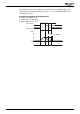
Hardware limit switches can also be used for homing. In this case, the hardware
limit switches are not evaluated by parameter
Fault Reaction 1143 during homing.
Warning! If evaluation of hardware limit switches is off, external control meas-
ures must be taken to ensure that in dangerous situations, e.g. hard-
ware limit switch overrun, safety device open, danger of loads falling
down, the drive is switched off immediately and a mechanical brake is
triggered, if necessary. Evaluation of the hardware limit switches does
not perform any safety functions and does not meet the requirements
of any standardized safety category.
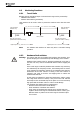
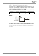
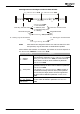
4.8.2.3 Move away from HW limit switches
If an axis is at a hardware limit switch, the drive is disabled for the direction from
where the limit switch was approached. In this case:
−
Acknowledge error and move in opposite direction in JOG mode (refer to section
4.5) or
−
Acknowledge error and start positioning in opposite direction
If you try to position in the former direction, error message "F1451 Clockwise Opera-
tion Locked" or "F1452 Anticlockwise Operation Locked" will be displayed.
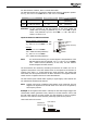
4.8.3 Software limit switches
For limitation of the travel range or protection of the machine, parameters
Positive
SW Limit Switch
1145 and Negative SW Limit Switch 1146 can be set. Travel
commands will be executed within this travel range only.
The parameters of the SW limit switches should be set such that the HW limit
switches and SW limit switches are not reached during operation.
The SW limit switches are related to the point of reference.
The SW limit switches are ready for operation if:
−
a homing operation was completed successfully and
−
one of the following operation modes is selected for parameter
Fault Reac-
tion
1144: "1 – Error Switch-Off", "2 – Shutdown, Error", "3 – Emergency-Stop,
Error", "10 – Warning".
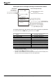
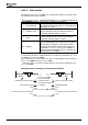
Parameter Setting
No. Description Min. Max. Fact. sett.
1145 Pos. SW Limit Switch -(2
31
-1) u 2
31
-1 u 65 536 u
1146 Neg. SW Limit Switch -(2
31
-1) u 2
31
-1 u -65 536 u
Application manual Positioning 9504/08