
Operating instructions

04/08 Application manual Positioning 91
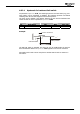
For each direction of motion, there is one HW limit switch.
The HW limit switches are connected to digital inputs which are assigned to parame-
ters
Neg. HW Limit Switch 1137 and Pos. HW Limit Switch 1138.
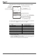
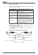
Parameter Factory setting Setting, e.g.
1138 Pos. HW Limit Switch 7 - Off 540 -
S4IND inverted
(Hardware)
1137 Neg. HW Limit Switch 7 - Off 541 -
S5IND inverted
(Hardware)
Attention! For the connection of HW limit switches to the inputs S4IND and
S5IND check the setting of parameter
Operation Mode 490 of speed
sensor 1. Set parameter
Operation Mode 490 = „0 - Off“. Also refer to
sections 3.4 and 3.5.1.4.
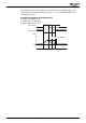
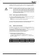
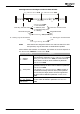
Input terminals for HW limit switches
1
2
3
4
5
6
7
X
2
1
0
A
+20 V/180 mA
GND 20 V
STOA (safety function
)
S2IND
Factory settings of the parameters
S3IND
S4IND
S5IND
P
os. HW Limit Switch
=
1138
Neg. HW Limit Switch
=
1137
"7 - Off"
"7 - Off"
Settings
P
os. HW Limit Switch
=
1138
"540 - S4IND inverted (Hardware)"
Neg. HW Limit Switch
=
1137
"541 - S5IND inverted (Hardware)"
Note: For wire-break monitoring, the inverted signals of the parameters of the
HW limit switches can be evaluated, e.g.
Pos. HW Limit Switch 1138 =
"540 - S4IND inverted (Hardware)". In this case, the limit switches
must be designed as break contacts.
The limit switches are monitored, considering the direction of rotation. An error is
signaled if the position of the limit switches does not correspond to the direction of
rotation of the motor, i.e. if limit switches are wired incorrectly. The positive HW
limit switch must be in positive direction for Motor Clockwise. The negative HW limit
switch must be in negative direction for Motor Anticlockwise.
The limit switch inputs evaluate static signals (no signal edges). Pulse switches are
not evaluated as hardware limit switches.
Note: Possibly overrunning of hardware limit switches is not monitored. This can
happen if the signal time of the limit switch is too short to be recognized by
the frequency inverter.
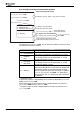
Example: If the negative limit switch is reached, the limit switch signal triggers the
selected fault reaction (parameter 1143). However, if the limit switch is overrun and
the limit switch signal is no longer present, the axis continues to move in negative
direction if the controller release and start positioning signals are still present.
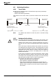
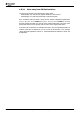
Limit switch cannot be overrun:
Limit switch
Mechanical
machine stop
Application manual Positioning 9104/08