
Operating instructions

04/08 Application manual Positioning 83
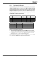
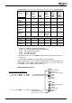
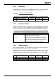
Standard terminal assignment in teach-in mode
Function
Control-
ler re-
lease
Jog
Clockwise
1232
Jog Anti-
clock-
wise
1233
Teach-In
Signal
1239
Neg. HW
Limit
Switch
1137
Pos. HW
Limit
Switch
1138
S2IND* S3IND* MFI1D* S5IND
2)
S4IND
2)
Drive dis-
abled
0 X X 0 0
(1)
0
(1)
Drive dis-
abled
X 1 1 X 0
(1)
0
(1)
JOG mode
clockwise
1 1 0 0 0
(1)
0
(1)
JOG mode
anticlock-
wise
1 0 1 0 0
(1)
0
(1)
Position is
saved
X X X
1
(positive
edge)
0
(1)
0
(1)
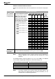
Error message, limit switch as make contact function
(brake contact function)
F1445
1)
X X X X 1
(0)
1
(0)
F1447
(F1446)
1)
X X X X 0
(1)
1
(0)
F1448
(F1446)
1)
X X X X 1
(0)
0
(1)
0 = Low / 1 = High / X = any / * = factory setting
1)
Also refer to chapter "Positioning Error Messages"
F1445: Pos. and Neg. HW-Lim Switch Simultaneously
F1446: Limit Switch Incorrect Wired
F1447: Pos. HW Limit Switch
F1448: Neg. HW Limit Switch
2)
Dependent on Operation Mode 490. Comply with the instructions in sections 3.4
and 3.5.1.4.
Assign S4IND and S5IND to the parameters for HW limit switches.
Values in parentheses
(0)
and
(1)
apply if the digital inputs for the limit switches are
configured as inverted inputs
(brake contact function)
, e.g. Positive HW Limit
Switch
1138 = "540 - S4IND inverted (Hardware)".
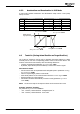
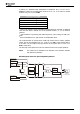
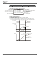
Input terminals for teach-in
STOB (safety function)
S1OUT
MFO1A
+10 V/4 mA
MFI1D
GND 10 V
1
2
3
4
5
6
7
X210A
+20 V/180 mA
GND 20 V
STOA (safety function)
S2IND
„ON“=JOG clockwise
Factory settings of the parameters
S3IND
S4IND
S5IND
S6IND
X210B
1
2
3
4
5
6
7
„ON“=JOG anticlockwise
„ON“= Save the
actual position value in
Target Position / Distance
1202
Teach-In-Signal
1239
= 76 - MFI1D„“
Jog Clockwise
= 71 - S2IND
1232
„“
Jog Anticlockwise
= 72 - S3IND
1233
„“
Application manual Positioning 8304/08