
Operating instructions

04/08 Application manual Positioning 77
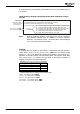
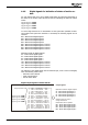
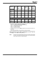
Standard Terminal Assignment JOG mode
Function
Control-
ler re-
lease
Jog-
Mode
Active
1231
Jog
Clock-
wise
1232
Jog Anti-
clockwise
1233
Neg. HW
Limit
Switch
1137
Pos. HW
Limit
Switch
1138
MFI1D* S2IND* S3IND* S5IND
2)
S4IND
2)
Drive dis-
abled
0 X X X 0
(1)
0
(1)
Drive dis-
abled
X 1 1 1 0
(1)
0
(1)
JOG mode
clockwise
1 1 1 0 0
(1)
0
(1)
JOG mode
anticlock-
wise
1 1 0 1 0
(1)
0
(1)
Error message, limit switch as make contact function
(brake contact function)
F1445
1)
X X X X 1
(0)
1
(0)
F1447
(F1446)
1)
X X X X 0
(1)
1
(0)
F1448
(F1446)
1)
X X X X 1
(0)
0
(1)
0 = Low / 1 = High / X = any / * = factory setting
1)
Also refer to chapter "Positioning Error Messages"
F1445: Pos. and Neg. HW-Lim Switch Simultaneously
F1446: Limit Switch Incorrect Wired
F1447: Pos. HW Limit Switch
F1448: Neg. HW Limit Switch
2)
Dependent on Operation Mode 490. Comply with the instructions in sections 3.4
and 3.5.1.4.
Assign S4IND and S5IND to the parameters for HW limit switches.
Values in parentheses
(0)
and
(1)
apply if the digital inputs for the limit switches are
configured as inverted inputs
(brake contact function)
, e.g. Positive HW Limit
Switch
1138 = "540 - S4IND inverted (Hardware)".
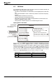
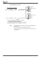
Note: JOG mode can be started without homing. The hardware limit switches
are active; the software limit switches relate to the reference position
and are active only after a homing operation.
Application manual Positioning 7704/08