
Operating instructions

04/08 Application manual Positioning 75
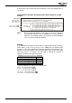
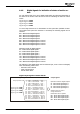
Example 1:
Digital signal 3 is to indicate that the target position was reached. When the position
is reached, the output signal is to be "1". When the position is not reached, the out-
put signal is to be "0".
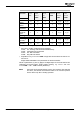
As soon as the target position is reached, the output is to be switched on, i.e. tens
digit is _1_. When the motion block is started, it is assumed that the target position
has not been reached, i.e. unit digit is __2. At the end of the motion block, the tar-
get position is unchanged; i.e. hundreds digit 0__. If you combine these digits you
get Operation Mode 012.
For this reason parameter
Digital Signal 3 1247 = 12.
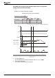
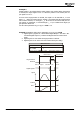
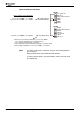
Example 2: Operation mode 120 for parameter
Digital Signal 1 1218
1. Digital signal 1 (signals "62 – Motion Block Digital Output 1" and "891 – Mo-
tion Block Digital Output 1") remains unchanged when the motion block
starts.
2.
Digital signal 1 is reset when the target position is reached.
3. Digital signal 1 is set at the end of the motion block (incl. delay).
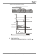
Target Position
Reached
Digital Signal 1
Position
Speed
Pos. 1
Delay
Motion block 1
Start: unchanged
1.
2.
3.
Ref.reached: off
End: on
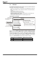
Motion block 2
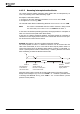
Digital Signal 1
1218
D
elay
1212
Motion block 1
1000 ms
120 - Start: --- Ref.reached: off End: on
Delay: Next Motion
Block
1213
2
1000 ms
Application manual Positioning 7504/08