
Operating instructions


66 Application manual Positioning 04/08
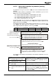
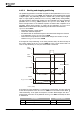
4.4.4 Input and output signals for motion blocks
The controller enables the execution of individual orders, repetition of motion blocks
and automatic sequence of motion blocks.
The motion block for the motion order can be selected via digital inputs or parame-
ters. The terminal assignment (without selection of motion block) is shown in the
following table.
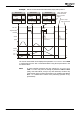
Terminal assignment for motion mode
Function
Control-
ler re-
lease
Start
Position-
ing 1222
Stop
Position-
in
g
1223
Touch
probe
Neg. HW
Limit
Switch
1137
Pos. HW
Limit
Switch
1138
S2IND* S3IND* S3IND** S5IND
3)
S4IND
3)
Drive dis-
abled
0 X X X 0
(1)
0
(1)
Positioning
is started
and
processed
(
4.4.5.1)
1 1 0 0 0
(1)
0
(1)
Touch probe
event is
processed
(
4.4.1.3)
1 1 0
edge
(parameter
1208)
1)
0
(1)
0
(1)
Positioning
is stopped
(
4.4.5.1)
1 1 1 X 0
(1)
0
(1)
Error message, limit switch as make contact function
(brake contact function)
F1445
2)
X X X X 1
(0)
1
(0)
F1447
(F1446)
2)
X X X X 0
(1)
1
(0)
F1448
(F1446)
2)
X X X X 1
(0)
0
(1)
0 = Low / 1 = High / X = any / * = factory setting
** = When the touch probe input (S3IND fixed) is used, parameterization of
Stop
Positioning
1223 (factory setting S3IND) must be changed.
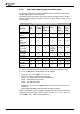
1)
Setting of Motion Mode 1208 = 2, 3, 12 or 13
2)
Also refer to chapter "Positioning Error Messages"
F1445: Pos. and Neg. HW-Lim Switch Simultaneously
F1446: Limit Switch Incorrect Wired
F1447: Pos. HW Limit Switch
F1448: Neg. HW Limit Switch
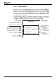
3)
Dependent on Operation Mode 490. Comply with the instructions in sections 3.4
and 3.5.1.4.
Assign S4IND and S5IND to the parameters for HW limit switches.
Values in parentheses
(0)
and
(1)
apply if the digital inputs for the limit switches are
configured as inverted inputs
(brake contact function)
, e.g. Positive HW Limit
Switch
1138 = "540 - S4IND inverted (Hardware)".
Application manual Positioning 04/0866