
Operating instructions

48 Application manual Positioning 04/08
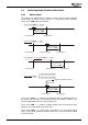
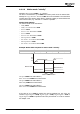
4.4.1.5 Combination with electronic gear
Positioning operation modes 10 to 14 and 20 to 24 (parameter
Motion Mode 1208)
are combined with the electronic gearing function.
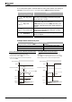
Operation modes 10 to 14,
“Gearing”
Operation modes 20 to 24,
“Gearing, direct synchronisation”
Synchronisation at attaining the master
speed
Direct synchronization at the start of a
motion block
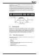
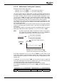
Operation modes 10 to 14, “Gearing”
The drive accelerates the master speed at the ramps parameterized in the motion
block. As soon as the master speed is reached for the first time, the drive is syn-
chronized with the master drive. The slave is engaged at the current position and
operates at a synchronous angle with the master. In the case of a relative position-
ing operation, this engaging position is used as the start position.
The acceleration and deceleration for synchronization occurs according to the char-
acteristic of an S-shaped curve.
Logic signal "57 – In Gear" signals synchronous operation and can be output via a
digital output. Logic signal "624 – In Gear" can be used for logic functions.
During synchronous operation, the ramps parameterized in the motion block are
deactivated. Acceleration and deceleration are defined by the master.
The slave unit calculates the delayed starting point internally from the parameterized
target position and the corresponding delay. As soon as this point is reached, the
unit disengages from the master and starts the deceleration. Logic signals "57 – In
Gear" and "624 – In Gear" are reset.
The drive speed is limited by the value adjusted for parameter
Maximum Frequency
419, even if the master drive exceeds this value. Logic signals "57 – In Gear" and
"624 – In Gear" are reset in this case.
Operation modes 20 to 24, “Gearing, direct synchronisation”
The drive accelerates the master speed at the ramps parameterized in the motion
block. At the start of a motion block the drive is sychronised with the master drive
directly. The master speed is processed by the position controller directly.
The acceleration and deceleration for synchronization occurs according to the char-
acteristic of an S-shaped curve.
Logic signal "57 – In Gear" signals synchronous operation and can be output via a
digital output. Logic signal "624 – In Gear" can be used for logic functions.
During synchronous operation, the ramps parameterized in the motion block are
deactivated. Acceleration and deceleration are defined by the master.
The drive speed is limited by the value adjusted for parameter
Maximum Frequency
419, even if the master drive exceeds this value. Logic signals "57 – In Gear" and
"624 – In Gear" are reset in this case.
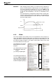
For jerk reduction the output of the position controller can be limited via Parameter
Limitation 1118. The value limits the speed for compensation of the position devia-
tion during synchronisation. Refer to chapter 4.12 “Position Controller”.
Application manual Positioning 04/0848