
Operating instructions


04/08 Application manual Positioning 37
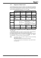
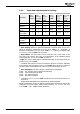
Input and output signals for homing
Homing Mode
1130
Operation Mode
1220
Homing
Home-Offset
1131
Fast Speed
1132
Creep Speed
1133
Acceleration
1134
Ramp Rise Time
1135
Input si
g
nals Output si
g
nals
Operation modes for di
g
ital outputs
:
59 - Homing Done
159 - Inv. Homing Done
Start Homing (manual)
1235
Home Switch
1139
Pos. HW Limit Switch
1138
Neg. HW Limit Switch
1137
Signal source:
614 - Homing Done
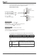
Assign
operation mode
Assign digital input signals or
logic signals to the parameters.
Home switch or limit switch
and speed sensor reference signal
Home switch or limit switch
without speed sensor reference signal
Speed sensor reference signal
Actual position
1 ... 14:
17 ... 30:
33, 34:
35:
Homing Modes
Assign
operation mode
1 - manual
2 - automatic
Attention! During manual homing, do not reset the homing control signal (pa-
rameter
Start Homing (manual) 1235). The control signal must be
present until the "Homing Done" is signaled. Otherwise, homing is
stopped. Without successful homing, no positioning operation can be
started, i.e. error message "F1570 No Homing Done" will be displayed
if you try to start a positioning operation.
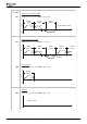
4.2.3 Homing mode
Via parameter Homing Mode 1130, you can define which signal will set the refer-
ence position, the direction in which the search for the point of reference is to be
started, as well as the condition for reversing the direction for the reference position.
Possible signals for setting the reference position:
− Negative hardware limit switch (anticlockwise)
− Negative hardware limit switch (clockwise)
− Home switch
− Zero pulse of an encoder
For the homing mode suitable for the relevant application, refer to chapter "List of
Homing Modes".
Application manual Positioning 3704/08