
Operating instructions

18 Application manual Positioning 04/08
3.5.1 Getting started
In order to use the positioning function, you must start the frequency inverter in
Configuration 240, 440 or 540. If required, perform a motor measurement. Several
functions will be readjusted as soon as you set up the configuration of the position-
ing operation. This includes the functions of the digital inputs.
Warning! Ensure that your parameterization corresponds to the connected termi-
nals.
For commissioning, you must select different configurations for the following cases:
Case Description
Possible Configuration 30
1 Motor encoder is position encoder at the
same time
240, 540
2 Two different encoders for motor and
positioning
240, 540
3 No motor encoder, external encoder for
positioning
440
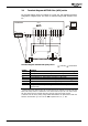
3.5.1.1 Motor encoder is position encoder at the same time
In slip-free systems, the motor encoder can be used as position encoder at the same
time. By using one encoder for both functions, the overall costs can be reduced.
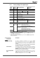
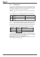
Configuration 30 = 240 | 540, motor encoder = position encoder
Encoder 1 Encoder 2 Motor controller
Operation Mode
490
Operation Mode
493
Actual Speed Source 766
Division Marks
491
Division Marks
494
Actual Position Source 1141 =
“0 - As P. 766 Actual Speed Source”
Level 495
In the corresponding parameters, set up the properties of the encoders according to
the wiring of Encoder 1 or Encoder 2. The parameters of Encoder 2 are available
only if the corresponding extension module is connected.
Adjust parameter
Actual Speed Source 766 to connected encoder.
Adjust parameter
Actual Position Source 1141 to "0 - As P. 766 Actual Speed
Source" (corresponds to factory settings).
Application manual Positioning 04/0818