
Operating instructions

04/08 Application manual Positioning 17
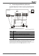
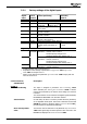
Digital signals for status indication
Digital signals can be influenced depending on the status of a motion order. For
example, a digital signal can be parameterized such that it signals reaching of the
target position or the end of the motion block.
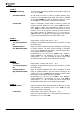
JOG mode
The drive is operated manually via two digital inputs at a parameterizable, fixed
speed. This enables for example functional tests for commissioning and approaching
of positions for teach-in mode.
Teach-In
With this function, any position approached can be entered directly in a motion
block as a target position. The required position can be approached in JOG mode.
The current position value is saved as the target position when an increasing edge
is present on the teach-in terminal.
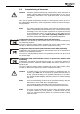
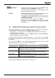
Homing
To determine the drive speed and position, the frequency inverter captures the sig-
nals from position sensors such as incremental encoders or resolvers. When the
frequency inverter is switched on, there is no relation between the position sensor
and the mechanical position of the axis. In order to determine an absolute point of
reference (reference position) for the positioning operation, a homing operation
must be performed. All absolute position data is referred to this reference position.
By selecting a certain homing mode, you can define in which direction the reference
position is to be found and which type of switch (limit switch, home switch) is used.
In the homing operation, the drive moves to the reference position and stops there.
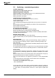
Monitoring
To limit the motion range and protect the machine, limit switches are connected to
the digital input terminals of the frequency inverter. The behavior of the drive when
reaching the limit switches is parameterizable (e.g. error switch-off, shut down).
Software limit switches enable monitoring of the permissible motion range. Position-
ing commands will be executed only within the range defined by parameters. The
software limit switches are active only after a successful homing operation.
The adjustable target window monitors the current position after performance of a
positioning operation. Reaching of the required position is signaled only if the cur-
rent position is within the target window.
The contouring error monitoring function monitors the maximum permissible devia-
tion of the current position and the required position. This monitoring function de-
termines how accurately the positioning operation must be performed.
Application manual Positioning 1704/08