
Operating instructions

162 Application manual Positioning 04/08
6.7 Positioning Warning Status
Warnings of the positioning functions are displayed in the error environment by pa-
rameter
Application Warning Status 367 and can be used for an early message of a
critical operational condition. Combinations of various warnings can be created in
parameter
Create Appl. Warning Mask 626. If a warning is present, this is indicated
by the flashing red LED and the display field WARN of the control unit KP500.
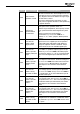
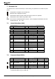
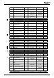
Meaning of code displayed by parameter
Application Warning Status 367:
Code Warning status
A 0000 NO WARNING No warning message present.
A 0002 SW-LIM CW
The positive SW limit switch was reached during clockwise
operation of the motor (parameter
Positive SW limit switch
1145).
A 0004 SW-LIM CCW
The negative SW limit switch was reached during anti-
clockwise operation of the motor (parameter
Negative SW
limit switch
1146).
A 0008 HW-LIM CW
The positive HW limit switch was reached during clockwise
operation of the motor (parameter
Positive HW limit
switch
1138).
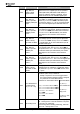
A 0010 HW-LIM CCW
The negative HW limit switch was reached during anti-
clockwise operation of the motor (parameter
Negative HW
limit switch
1137).
A 0020 CONT
The contouring error monitoring range adjusted with pa-
rameter
Warning Threshold 1105 was left.
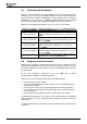
6.8 Diagnosis and fault clearance
Diagnosis and monitoring in operation and in the case of error messages is repre-
sented clearly by parameter groups "Actual Values of Frequency Inverter" and "Ac-
tual Values of Machine". In these parameter groups, the operating status and values
can be analyzed.
For the error messages of parameter
Current Error 259, refer to section
"Positioning Error Messages" of positioning function.
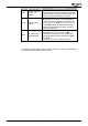
In the case of an error message, always perform the following steps:
•
Check wiring and units for damage.
• Check if all units (including bus clients, encoders, etc.) are supplied with power
and ready for operation.
•
If a limit switch is active, the corresponding direction of rotation is disabled.
First, the drive must be moved into the permissible range in opposite direction
(e.g. in JOG mode).
•
Check if homing was completed and "614 – Homing Done" was signaled.
The positioning functionality is very complex. Due to this complexity in combination
with other devices (e.g. PLC), diagnosis must generally be performed across the
whole system.
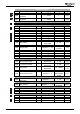
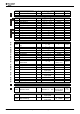
The following descriptions of anomalous operating behaviours help to find the cause
of failures.
Application manual Positioning 04/08162