
Operating instructions

160 Application manual Positioning 04/08
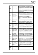
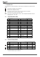
Error Error message Description/Action
F1470
Neg. HW-Lim.
Switch: Illegal
Signal Source
Neg. HW Limit Switch 1137 is set to an illegal logic
signal source or to a digital input of an expansion
module (EM-S1IND, EM-S2IND or EM-S3IND) al-
though no expansion module is installed. The pa-
rameter must be set to an available digital input.
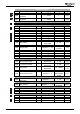
F1471
Neg. HW-Lim.
Switch: Input dis-
abled by PWM-/FF-
Input
The digital input for
Neg. HW Limit Switch 1137 is
set as PWM- or repetition frequency input. Set pa-
rameter
Operation Mode 496 of the PWM-/ repeti-
tion frequency input to “0 - off” or to another digital
input to use the digital input as HW-limit switch in-
put.
F1472
Neg. HW-Lim.
Switch: Input dis-
abled by Index-
Contr.
The digital input for
Neg. HW Limit Switch 1137 is
set as input for index control. Check the settings of
Operation Mode 598 of the index control and Index
Controller Release
96. Alternatively use another
digital input for the connection of the HW-limit
switch.
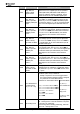
F1473
Neg. HW-Lim.
Switch: Wrong
Op.-Mode for MFI1
The multifunction input MFI1 at terminal X210B.6 is
set as voltage input or current input via parameter
Operation Mode 452. Set Operation Mode 452 to
“3 - Digital Input” to use the multifunction input as
HW-limit switch input.
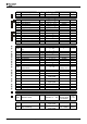
F1474
Neg. HW-Lim.
Switch: Input dis-
abled by En-
coder 1
The digital input for
Neg. HW Limit Switch 1137 is
set as encoder input. Set
Operation Mode 490 of
the speed sensor 1 to “0 - off” to use the digital input
as HW-limit switch input. Alternatively use another
digital input for the connection of the HW-limit
switch.
F1475
Neg. HW-Lim.
Switch: Input dis-
abled by En-
coder 2
The digital input for
Neg. HW Limit Switch 1137 is
set as encoder input. Set
Operation Mode 493 of
the speed sensor 2 to “0 - off” to use the digital input
as HW-limit switch input. Alternatively use another
digital input for the connection of the HW-limit
switch.
F1476
Neg. HW-Lim.
Switch: Wrong
Op.-Mode for EM-
S1IOD
The digital port EM-S1IOD of an expansion module is
misadjusted for the evaluation of a HW-limit switch.
The parameter
Operation Mode 558 must be set to
“0 - input”.
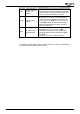
The parameterized behavior for Delay or “Next Mo-
tion Block” (after event) is effective.
−
A delay is expired or an event is triggered and
− one of the following operation modes is assigned
to a parameter for “Next Motion Block”
Parameter for “Next Motion Block”: Operation Mode:
-1 (Minus 1) –
Error Switch-Off
-2 (Minus 2) –
Stop, error
F15xx
User-Defined Error
in Motion Block
xx (1
≤ xx ≤ 32)
Delay: Next Motion Block 1213,
Event 1: Next Motion Block 1215,
Event 2: Next Motion Block 1217,
Int.-Event 1: Next Motion
Block
1262,
Int.-Event 2: Next Motion
Block
1265
-3
(Minus 3) – Em.
stop, error
F1570 No Homing Done
Positioning was started without prior homing. Signal
"59 – Homing Done" is not set and there is no point
of reference for positioning.
Start homing. Before starting positioning, wait until
signal "59 – Homing Done" is set.
Application manual Positioning 04/08160