
Operating instructions

04/08 Application manual Positioning 159
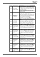
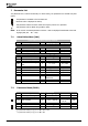
Error Error message Description/Action
F1452
Anti-Clockwise
Operation Locked
Negative hardware limit switch or negative software
limit switch reached. After acknowledgement of error
it was tried to move in negative direction (anticlock-
wise). Negative direction is disabled as long as nega-
tive limit switch is active.
Move axis in defined travel range again: In JOG
mode, move in opposite direction or start positioning
in opposite direction.
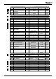
F1453
System bus-
Synchronization
not activated
Parameter
Master Position Source 1122 of elec-
tronic gear is set to operation mode "11 -
RxPDO1.Long1 extrapolated", but frequency inverter
is not synchronized with data telegrams of system
bus.
Switch on system bus synchronization:
Set Parameter
Operation Mode 1180 to "1 -
RxPDO1" or "10 - SYNC" (chapter "Master position
source").
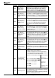
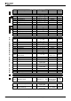
F1460
Pos. HW-Lim.
Switch: Illegal
Signal Source
Pos. HW Limit Switch 1138 is set to an illegal logic
signal source or to a digital input of an expansion
module (EM-S1IND, EM-S2IND or EM-S3IND) al-
though no expansion module is installed. The pa-
rameter must be set to an available digital input.
F1461
Pos. HW-Lim.
Switch: Input dis-
abled by PWM-/FF-
Input
The digital input for
Pos. HW Limit Switch 1138 is
set as PWM- or repetition frequency input. Set pa-
rameter
Operation Mode 496 of the PWM-/ repeti-
tion frequency input to “0 - off” or to another digital
input to use the digital input as HW-limit switch in-
put.
F1462
Pos. HW-Lim.
Switch: Input dis-
abled by Index-
Contr.
The digital input for
Pos. HW Limit Switch 1138 is
set as input for index control. Check the settings of
Operation Mode 598 of the index control and Index
Controller Release
96. Alternatively use another
digital input for the connection of the HW-limit
switch.
F1463
Pos. HW-Lim.
Switch: Wrong
Op.-Mode for MFI1
The multifunction input MFI1 at terminal X210B.6 is
set as voltage input or current input via parameter
Operation Mode 452. Set Operation Mode 452 to
“3 - Digital Input” to use the multifunction input as
HW-limit switch input.
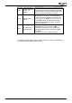
F1464
Pos. HW-Lim.
Switch: Input dis-
abled by En-
coder 1
The digital input for
Pos. HW Limit Switch 1138 is
set as encoder input. Set
Operation Mode 490 of
the speed sensor 1 to “0 - off” to use the digital input
as HW-limit switch input. Alternatively use another
digital input for the connection of the HW-limit
switch.
F1465
Pos. HW-Lim.
Switch: Input dis-
abled by En-
coder 2
The digital input for
Pos. HW Limit Switch 1138 is
set as encoder input. Set
Operation Mode 493 of
the speed sensor 2 to “0 - off” to use the digital input
as HW-limit switch input. Alternatively use another
digital input for the connection of the HW-limit
switch.
F1466
Pos. HW-Lim.
Switch: Wrong
Op.-Mode for EM-
S1IOD
The digital port EM-S1IOD of an expansion module is
misadjusted for the evaluation of a HW-limit switch.
The parameter
Operation Mode 558 must be set to
“0 - input”.
Application manual Positioning 15904/08