
Operating instructions


158 Application manual Positioning 04/08
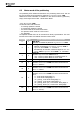
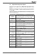
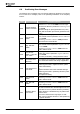
6.6 Positioning Error Messages
The following error messages may occur during positioning operations. For informa-
tion on other error messages, refer to the operating instructions of the frequency
inverter.
Error Error message Description/Action
F0404
Control Deviation
Position Controller
The current contouring error has exceeded the value
defined in
Error Threshold 1106 for a time longer
than the time defined in parameter
Contouring Error
Time
1119.
Optimize settings for speed (parameters 419, 1203,
1236) and acceleration pilot control (parameters 725
to 727)
F1442
Pos. SW-Limit
Switch
Current position or target position of current motion
order exceeds value for parameter
Positive SW Limit
Switch
1145.
Check
Target Position / Distance 1202 parameter
values entered in motion blocks.
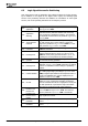
F1443
Neg. SW-Limit
Switch
Current position or target position of current motion
order exceeds value for parameter
Negative SW Lim-
it Switch
1146.
Check
Target Position / Distance 1202 values en-
tered in motion blocks.
F1444
Pos. SW-Lim.
Switch < Neg. SW-
Lim. Switch
Value of parameter
Positive SW Limit Switch 1145
smaller than value of parameter
Negative SW Limit
Switch
1146.
Check and, if necessary, change parameter values.
F1445
Pos. and Neg. HW-
Lim Switch Simul-
taneously
Both hardware limit switches are active at the same
time. Check limit switches and wiring of application.
F1446
Limit Switch Incor-
rect Wired!
Positive hardware limit switch activated although
positioning performed in negative direction (motor
rotates anticlockwise).
Or:
Negative hardware limit switch activated although
positioning performed in positioning direction (motor
rotates clockwise).
Check plant and wiring.
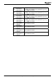
F1447
Pos. HW Limit
Switch
The positive hardware limit switch was reached.
Check
Target Position / Distance 1202 values en-
tered in motion blocks.
F1448
Neg. HW Limit
Switch
The negative hardware limit switch was reached.
Check
Target Position / Distance 1202 values en-
tered in motion blocks.
F1451
Clockwise Opera-
tion Locked
Positive hardware limit switch or positive software
limit switch reached. After acknowledgement of error
it was tried to move in positive direction (clockwise).
Positive direction is disabled as long as positive limit
switch is active.
Move axis in defined travel range again: In JOG
mode, move in opposite direction or start positioning
in opposite direction.
Application manual Positioning 04/08158