
Operating instructions

14 Application manual Positioning 04/08
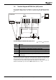
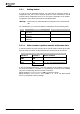
X210A.5
Stop Positioning The drive stops at the current position at deceleration ramp set in
Deceleration 1206.
JOG Anticlockwise In JOG mode, the drive is moved in negative direction (anti-
clockwise) at an adjustable fixed speed. JOG mode is activated
via terminal X210B.6. In teach-in operation modes (
Operation
Mode
1221), the JOG function is activated automatically.
Touch probe Input for momentary contact switch or sensor for setting the
reference position. Effective in
Motion Mode 1208 with touch-
probe. Rising or falling edge (depending on setting of
Motion
Mode
1208) on input sets the point of reference at the current
position. As soon as the signal is received, the drive moves by
the relative distance of parameter
Target Position/Distance
1202. Parameter configuration for digital signal "Stop Position-
ing" should be changed when touch probe mode is used.
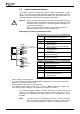
X210A.6
Encoder 1 Input Encoder 1 Track B, HTL, DC 12 … 30 V
or freely programma-
ble
Evaluation of parameterized functions if the terminal is not used
as encoder input.
Possible function:
Pos. HW Limit Switch
Input for positive hardware limit switch. Limitation of travel range
in positive direction. The drive reacts according to parameter
Fault Reaction 1143 when the switch is reached. Positive direc-
tion (clockwise direction) is disabled.
Set parameter
Pos. HW Limit Switch 1138 = “540 - S4IND in-
verted (Hardware)“. Set Parameter
Operation Mode 490 of
speed sensor 1 = “0 - Off”. If X210A.6 is used as encoder input
the HW limit switch function is not evaluated as this input.
X210A.7
Encoder 1 Input Encoder 1 Track A, HTL, DC 12 … 30 V
or freely programma-
ble
Evaluation of parameterized functions if the terminal is not used
as encoder input.
Possible function:
Neg. HW Limit Switch
Input for negative hardware limit switch. Limitation of travel
range in negative direction. The drive reacts according to pa-
rameter
Fault Reaction 1143 when the switch is reached. Nega-
tive direction (anticlockwise direction) is disabled.
Set parameter
Neg. HW Limit Switch 1137 = “541 - S5IND in-
verted (Hardware)“. Set Parameter
Operation Mode 490 of
speed sensor 1 = “0 - Off”. If X210A.7 is used as encoder input
the HW limit switch function is not evaluated as this input.
X210B.1
Home switch Input for reference cams. Marks the point of reference for abso-
lute positioning. Via parameter
Home Switch 1139, the logic
status of the switch is evaluated.
or Encoder 1 Input Encoder 1 Zero Track Z, HTL, DC 12 … 30 V.
Select one of the settings 1001 … 1132 (with reference pulse) for
parameter
Operation Mode 490.
Application manual Positioning 04/0814