
Operating instructions


156 Application manual Positioning 04/08
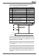
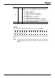
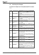
6.5 Logic Signal Sources for Positioning
Logic signal sources can be assigned to the software functions for further process-
ing. In addition to the signals on the digital control inputs, the following signal
sources of the positioning functions are available. For information on other signal
sources, refer to the operating instructions of the frequency inverter.
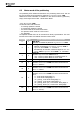
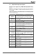
Logic signal Function
215 -
Warning Mask,
Application
Message of the configurable parameter
Create Warning
Mask Application
626.
216 -
Application
Warning
Warning messages of error/warning behavior function
(HW limit switches, SW limit switches and contouring
error monitoring of positioning function). The warnings
are displayed as actual values via parameter
Application
Warnings
273.
282 -
Target Position
Reached
Target Position / Distance 1202 of a positioning opera-
tion was reached, and current position is within the
range set in parameter
Target window 1165 for a mini-
mum period of
Target window time 1166.
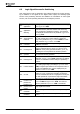
604 -
Warning Position
Controller
The contouring error monitoring
Warning Threshold
1105 was exceeded.
614 - Homing Done
Reference position is set. This is done by homing (pa-
rameters 1220 and 1130 to 1135) or in
Motion Mode
1208 with touch probe (operation modes 2, 3, 12, 13)
by taking over current position as reference position
615 -
Homing Re-
quested
A homing operation was started. The signal is reset at
the end of the homing operation.
616 - Phasing Done
Master position evaluated by slave was offset by value of
parameter
Phasing: Offset 1125. Parameters of phasing
function are available in master settings of positioning
function.
617 - Latched Position
The stored actual position value of the drive. With a ris-
ing or falling signal edge (according to
Operation Mode
1280) at digital input S2IND the actual position value is
stored in the EEPROM. The value is displayed via pa-
rameter
Latched Position 1281.
624 - In Gear
In
Motion Mode 1208 with electronic gear (operation
modes 10 to 14), synchronous operation of electronic
gear was reached. Slave drive is engaged at current posi-
tion and operates at a synchronous angle with master.
Slave drive is synchronized with master frequency.
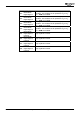
876 -
Position Com-
parator Out
Current position value is in the range between
On-
Position
1243 and Off-Position 1244. The value se-
lected in parameter
Hysteresis 1245 is considered.
877 -
Position Com-
parator Out in-
verted
Logic signal 876 inverted.
887 -
MBC: Start
Clockwise
Status message of clockwise operation of positioning
control.
888 -
MBC: Start Anti-
clockwise
Status message of anticlockwise operation of positioning
control.
Application manual Positioning 04/08156