
Operating instructions

04/08 Application manual Positioning 13
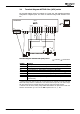
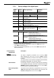
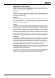
3.3.1 Factory settings of the digital inputs
Control input functions
Digital
Input
Control
terminal
Control positioning JOG mode /
Teach-in
Digital inputs of frequency inverter:
S1IND X210A.3 Digital input STOA for safety function
S2IND X210A.4 Start
Positioning
Store actual
position value
3)
JOG Clockwise
S3IND X210A.5 Stop Positioning,
Touch probe
1)
JOG Anticlockwise
S4IND X210A.6 Freely programmable or
Encoder 1 Track B
2)
S5IND X210A.7 Freely programmable or
Encoder 1 Track A
2)
S6IND X210B.1 Home switch or
Encoder 1 Zero Track Z
2)
X210B.2 Digital input STOB for safety function
MFI1D X210B.6 Change-over position con-
trol/JOG mode (JOG mode ac-
tive)
Teach-in signal in teach-
in mode
Digital inputs extension module:
EM-S1IND Motion Block Change-Over 1
Alternative: - Encoder 2 Zero Track Z
- Fixed frequency change-over 1
- Fixed percentage value change-over 1
EM-S2IND Motion Block Change-Over 2
Alternative: - Encoder 2 Track A
- Fixed frequency change-over 2
- Fixed percentage value change-over 2
EM-S3IND
depending
on module
Motion Block Change-Over 3
Alternative: - Encoder 2 Track B
1)
Comply with the notes in section 4.4.1.3.
2)
Dependent on the settings of parameters
Configuration 30 and Operation
Mode
490. See chapter 3.5.1.4.
3)
Switch on the function via parameter Operation Mode 1280. Comply with the
notes in section
4.13.
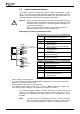
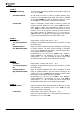
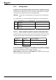
Control terminal/ Description
Identification
X210A.4
Start Positioning
The input is assigned to parameter
Start Positioning 1222.
When activated, the
Starting-Record Number 1228 or another
motion block selected by the motion block change-over function
is started.
The motion blocks can be switched via digital inputs EM-S1IND,
EM-S2IND and EM-S3IND of an extension module.
JOG Clockwise In JOG mode, the drive is moved in positive direction (clockwise)
at an adjustable fixed speed. JOG mode is activated via terminal
X210B.6. In teach-in operation modes (
Operation Mode 1221),
the JOG function is activated automatically.
Store actual position
value
The function can be switched on via parameter Operation Mode
1280. With signal edge the actual position value is stored in the
EEPROM and displayed via
Latched Position 1281.
Application manual Positioning 1304/08