
Operating instructions

12 Application manual Positioning 04/08
3.3 Control Inputs and Outputs
The modular structure of the frequency inverters enables a wide spectrum of appli-
cations on the basis of the available hardware and software functionality. The func-
tionality of the control inputs and outputs described in the "Quick Start Guide" and
operating instructions is extended in the described configurations.
Caution!
Switch off power supply before connecting or disconnecting the control
inputs and outputs. Verify that the keyed control inputs and outputs are
deenergized before connecting or disconnecting them. Otherwise, com-
ponents may be damaged.
The unit may only be connected with the power supply switched off.
Make sure that the frequency inverter is discharged.
ACU frequency inverters of ACTIVE Cube series
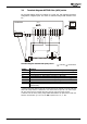
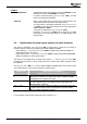
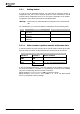
Control terminal X210A
X210A.1 +20 V voltage output (I
max
=180 mA) or
input for external power supply 24 V
X210A.2 GND 20 V/ GND 24 V (ext.)
X210A.3 Safety function, digital input STOA
X210A.4 − Start Positioning
− JOG Clockwise
− Store actual position value (latching)
X210A.5 − Stop Positioning
− JOG Anticlockwise
− Touch probe
X210A.6 Encoder 1 Track B
1)
or
freely programmable
2)
X210A.7 Encoder 1 Track A
1)
or
freely programmable
2)
Control terminal X210B
X210B.1 Home switch
3)
or
Encoder 1 Zero Track Z
4)
X210B.2 Safety function, digital input STOB
X210B.3 Operating message
X210B.4 Analog signal of actual frequency
X210B.5 Supply voltage +10V
X210B.6 − Change-over position control/JOG
mode (JOG mode active)
− Teach-In-Signal
S7IND
S1OUT
MFO1A
+10 V/4 mA
MFI1D
GND 10 V
1
2
3
4
5
6
7
X21
0
A
+20 V / +24 V ext.
GND 20 V / GND 24 V ex
t
STOA
STOB
S1IND
S2IND
S3IND
S4IND
S5IND
S6IND
X210B
1
2
3
4
5
6
7
+
B
-
A
Z
X210B.7 Ground 10 V
1)
Factory setting in configuration 240
2)
If no speed sensor is connected to S4IND/S5IND the digital inputs can be used freely program-
mable (e.g. for hardware limit switches).
3)
Factory setting in configurations 240, 440 and 540
4)
For evaluation of an encoder zero track an Operation Mode 490 for speed sensor 1 higher than
1000 must be selected. Linking of other functions to this input are not active.
The connection diagram describes the default assignment of control terminals and
functions in the different configurations positioning control. According to the re-
quirements of the application, the other functions can be assigned to the control
terminals.
Note:
In order to fully use the positioning functions, an optional extension
module is required. This module enables, for example, encoder evalua-
tion, motion-block change-over or reference percentage change-over.
Application manual Positioning 04/0812