
Operating instructions

04/08 Application manual Positioning 119
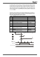
5.4 Terminology
To enable a better understanding of the homing modes, the terms used are ex-
plained in the following.
Home switch active = 1 "High" signal is present
inactive = 0 "Low" signal is present
not used In this homing mode, no home switch is used
Limit switch Travel limit.
Hardware limit
switches
Travel limit. Design: Initiators connected to
digital inputs.
Software limit
switches
Travel limit, managed centrally in frequency
inverter. Only active after homing. Software
limit switches stop the travel operation before
the hardware limit switches as an additional
safety function.
Ref. signal Pulse which occurs once every encoder rota-
tion. Increases homing accuracy.
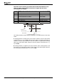
Direction of rota-
tion reversal
The search direction is changed when a status
change (e.g. "limit switch reached”) has oc-
curred. This indicates that the home position is
in opposite direction.
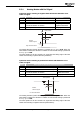
Search direction Positive
direction
Motor turns in positive direction
(clockwise when looking at shaft).
Negative
direction
Motor turns in negative direction
(anticlockwise when looking at shaft).
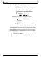
Edge Rising
edge
Status change of a signal from "0” to "1”.
Falling
edge
Status change of a signal from "1” to "0”.
Left
edge
Status change of a signal from "1" to "0" or
"0" to "1" in the case of a cam on the left side.
Right
edge
Status change of a signal from "1" to "0" or
"0" to "1" in the case of a cam on the right
side.
Speed Fast speed High speed at which the target is searched at
the beginning.
Creep speed Low speed at which the target is approached
exactly.
Application manual Positioning 11904/08