
Operating instructions

118 Application manual Positioning 04/08
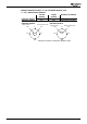
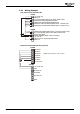
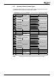
5.3 Graphic Overview of Homing Modes
Home switch
27
26
25
28
29
30
23
24
Home switch
22
21
20
19
Positive limit switch
18
Negative limit switch
17
14
3
4
5
6
7
8 9
10
11
1213
1
2
34
33
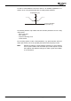
Encoder zero track
(Reference signal)
35
Actual position
P
P
N
N
P
P
N
N
N
NN
N
P
P
P
P
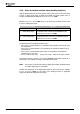
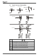
Zero track left or right of edge
Number of homing mode
Destination approached from left upon rising edge. When coming from
the right, direction is reversed when passing the edge.
Destination approached from right upon falling edge. When coming from
the left, direction is reversed when passing the edge.
Destination approached from right upon rising edge. When coming from
the left, direction is reversed when passing the edge.
Destination approached from left upon falling edge. When coming from
the right, direction is reversed when passing the edge.
P
Positive hardware limit switch is used for reversal of direction of rotation.
N
Negative hardware limit switch is used for reversal of direction of rotation.
Application manual Positioning 04/08118