
Operating instructions

04/08 Application manual Positioning 117
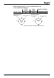
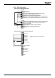
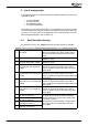
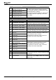
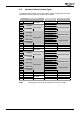
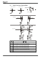
5.2 Overview Table of Homing Types
The following table provides an overview of which position is approached and which
limit switch is used for reversal of the direction of rotation.
No. Main destination Fine destination
(Ref. signal)
Limit Switch ?
1 Left Ref. signal right Left limit switch
2 Right
limit switch
Ref. signal left Right limit switch
3 Ref. signal left
4
Negative
Ref. signal right
5 Ref. signal right
6
Positive
home switch
Ref. signal left
Without limit switch
7 Ref. signal left
8
Left edge
Ref. signal right
9 Ref. signal left
10
Right edge
Ref. signal right
Right limit switch
11 Ref. signal right
12
Right edge
Ref. signal left
13 Ref. signal right
14
Left edge
home switch
Ref. signal left
Left limit switch
15 Reserved
16 Reserved
17 Left Falling edge Left limit switch
18 Right
limit switch
Falling edge Right limit switch
19 Falling edge
20
Negative
Rising edge
21 Falling edge
22
Positive
home switch
Rising edge
Without limit switch
23 Falling edge
24
Left edge
Rising edge
25 Rising edge
26
Right edge
Falling edge
Right limit switch
27 Falling edge
28
Right edge
Rising edge
29 Rising edge
30
Left edge
home switch
Falling edge
Left limit switch
31 Reserved
32 Reserved
33 Left
34 Right
ref. signal
35 Current position
Note: Homing types 17 to 30 do not evaluate any encoder ref. signal.
Application manual Positioning 11704/08