
Operating instructions

04/08 Application manual Positioning 9
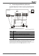
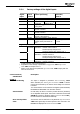
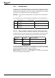
2.1 Terminal diagram ACTIVE Cube (ACU) series
The terminal diagram shows an example of a linear axis, with standard parameter
configuration of digital inputs. The sensor is evaluated using an EM extension mod-
ule.
ACTIVE Cube
RS232
X2
U
VW
X410A
EM
X410B
VPlus
1
2
34
5
67
X210A X210B
+20V
GND
S1IND
S2IND
S3IND
S4IND
S5IND
S6IND
S7IND
S1OUTD
MFO1A
10VRef
MFI1D
GND
1
2
34
5
67
STOA
S2 SMFI1DS3
S4S6S5
STOB
Terminal diagram ACTIVE Cube (ACU) series
: clockwise; : Anticlockwise
Switch Function
STOA Wire input S1IND as shut-down path STOA of safety function STO
1)
STOB Wire input S1IND as shut-down path STOB of safety function STO
1)
S2 Start positioning or clockwise operation in JOG mode
S3 Stop positioning or anticlockwise operation in JOG mode
S4 Limit switch for limitation of motion range in positive direction
2)
S5 Limit switch for limitation of motion range in negative direction
2)
S6 Home switch for homing, point of reference for absolute positioning
SMFI1D Change-over between positioning mode and JOG mode (JOG mode in
manual mode)
1)
Safety function STO (Safe Torque Off) is wired through two channels via inputs STOA and
STOB. This safety function is described in user manual "Safe Torque Off". The "Safe Torque
Off" user manual must be complied with when using the "Safe Torque Off" function.
2)
Different from the factory setting. Assign S4IND and S5IND to the parameters for HW limit
switches. Set Parameter Operation mode 490 of speed sensor 1 to „0 - Off“.
Application manual Positioning 904/08