
Operating instructions


70 06/05
7 Annex
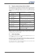
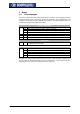
7.1 Error messages
T
he various control functions and methods and the hardware of the frequency inverte
r
contain functions which continuously monitor the application. As a supplement to the
messages documented in these operating instructions, the followin
g
failure keys are
activated by the EM-IO-02 expansion module.
Control connections
02 Reference value signal on analog input EM-S1INA faulty, check signal
30 Speed sensor signal 2 is faulty, check connections
31 One track of the speed sensor signal 2 is missing, check connections.
F14
32 Direction of rotation of speed sensor 2 wrong, check connections.
33 Speed sensor 2, divisions marks wrong, check speed sensor
34 Division marks of speed sensor signal 2 too low, check speed sensor.
35 Division marks of speed sensor signal 2 too high, check speed sensor.
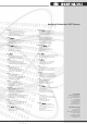
System bus
F21 nn Fault report to system bus master in fault in system bus slave
nn = Node ID of slave (hex)
System bus
00 Communication fault, system bus, timeout SYNC telegram
01 Communication fault, system bus, timeout RxPDO1
02 Communication fault, system bus, timeout RxPDO2
03 Communication fault, system bus, timeout RxPDO3
F22
10 Communication fault, system bus, bus OFF
Alongside the fault messa
g
es stated, there are further fault messa
g
es, however they
are only used for internal purposes and are not listed here. If you receive fault mes-
sages which are not listed here, please contact us by phone.