
Operating instructions


64 06/05
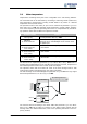
5.8 Status of the digital signals
The status of the digital signals can be read in decimal coding via the parameters
Digi-
tal inputs
250 and Digital outputs 254. The display of the di
g
ital input si
g
nals enables
checking the various control signals and their connections with the software functions
in question, in particular in commissioning.
After conversion of the decimal fi
g
ure into the binary system, bits 8, 9 and 10 displa
y
the states of the inputs EM-S1IND, EM-S2IND and EM-S3IND.
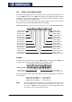
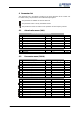
Coding of the status of the digital signals
8
7
6
5 4
3
2
0
Bit
15
14
13
12 11
10
9
Bit
control signal 2
( 2)decimal value
1
control signal 1
( 1)decimal value
control signal 3
(4)decimal value
control signal 5
( 16)decimal value
control signal 4
( 8)decimal value
control signal 6
( 32)decimal value
control signal 7
( 64)decimal value
control signal 8
( 128)decimal value
control signal 15
( 16384)decimal value
control signal 16
(decimal value 32768)
control signal 14
( 8192)decimal value
control signal 12
( 2048)decimal value
control signal 13
( 4096)decimal value
control signal 11
( 1024)decimal value
control signal 10
( 512)decimal value
control signal 9
( 256)decimal value
Example:
The actual value parameter
Digital inputs 250 displays the decimal value 640. Afte
r
conversion into the binary system, the following combination results:
1 0 0 0 0 0 0
BitBit
0
8
7
6
5 4
3
2
0151413
12 11
10
9
1
000000 01
Binary system:
control signal 8
(decimal value 128)
control signal 10
(decimal value 512)
The following status of the digital input signals of the EM-IO-02 expansion module has
been displayed
− Digital input EM-S1IND = 1 – control signal 8
− Digital input EM-S2IND = 0 – control signal 9
− Digital input EM-S3IND = 1 – control signal 10
Note: The three digital inputs of the EM-IO-02 expansion module can be used
for the evaluation of a speed sensor via the parameter
Operation mode
Speed sensor 2
493. The control si
g
nals are set to the lo
g
ical value zero
as a function of the selected operation mode.