
Operating instructions


06/05 63
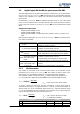
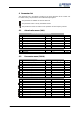
5.6 Frequency and percentage reference channel
T
he varied functions for the specification of the reference values are connected in the
various configurations by the frequency or percentage reference channel. The
Refer-
ence frequency source
475, and the Reference percentage source 476 determine the
additive connection of the available reference sources as a function of the installed
hardware.
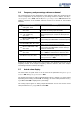
Operation mode Function
2 -
EM-S1INA,
analog abs. value
Reference source is the analog input EM-S1INA
4 -
MFI1A + EM-S1INA,
abs. value
Reference sources are the multifunctional input
MFI1A and the analog input EM-S1INA
12 -
EM-S1INA
+ FF (and/or FP),
abs. value
Reference sources are the analog input EM-S1INA
and fixed frequency FF (and/or the fixed percent-
age FP)
14 -
MFI1A + EM-S1INA + FF,
abs. value
Reference sources are the multifunctional input
MFI1A, analog input EM-S1INA and fixed frequency
FF
22 -EM-S1INA +MP, abs. value
Reference sources are the analog input EM-S1INA
and the motor potentiometer function MP.
24 -
MFI1A + EM-S1INA + MP,
abs. value
Reference sources are the multifunctional input
MFI1A, analog input EM-S1INA and the motor po-
tentiometer function MP
34 -
speed sensor 2 (F2),
abs. value
The frequency signals in
Operation mode Speed
sensor 2
493 are evaluated as a reference value.
35 -MFI1A + F2, abs. value
Reference sources are the multifunctional input
MFI1A and the frequency signals in
Operation
Mode Speed Sensor 2
493.
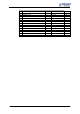
102 to 135 Operation modes with signs (+/-)
Alon
g
side the operation modes listed, those stated in the operatin
g
instructions of the
frequency inverter in the chapter "Frequency reference channel“, and in the chapte
r
"Percentage reference channel“ also apply.
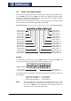
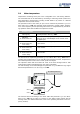
5.7 Actual value display
The actual value of speed sensor 2 can be read via the parameters
F
requency spee
d
sensor 2
219 and Speed, speed sensor 2 220.
The analog input signal on analog input EM-S1INA can be a volta
g
e or a current si
g
nal
depending on the setting of switch S3. Accordingly, the actual value parameter
Analo
g
input EM-S1INA
253 is displayed as a percentage.
The analog output signal on analog output EM-S1OUTA can be read via the actual
value parameter
Analog output EM-S1OUTA 266.