
Operating instructions


06/05 61
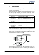
5.5 Digital inputs EM-SxIND for speed sensor EM-ENC
The three digital inputs of the EM-IO-02 expansion module can be set via the parame-
ter
Operation mode Speed sensor 2 493 and selection of the corresponding operation
mode for the evaluation of a unipolar 24V two-channel speed sensor (incremental
speed sensor).
For parameter analog mode 553, the additional operation mode 4 – abs. value speed
sensor 2 can be selected, which can output the abs. value of the speed sensor si
g
nal 2
in the range from 0.00 Hz to
maximum frequency 419 via the multifunctional output
MFO1.
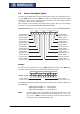
Assignment of the inputs:
− Digital input EM-S2IND: track A
− Digital input EM-S3IND: track B
− Digital input EM-S1IND: corresponding to the operation mode as a reference im-
pulse
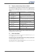
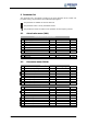
With the help of parameter
Operation mode Speed sensor 2 493, the following opera-
tion modes are available:
Operation mode Function
0 -Off
Speed measurement is not active; the di
g
ital inputs are
available for further functions.
4 -Quadruple evaluation
Two-channel speed sensor with reco
g
nition of direction
of rotation via track signals A and B;
four signal edges are evaluated per division mark.
104 -
Quadruple evaluation
inverted
A
s operation mode 4; the actual speed value is in-
verted. (Alternative to exchanging the track signals).
1004 -
Quadruple evaluation
with reference im-
pulse
Two-channel speed sensor with reco
g
nition of direction
of rotation via track signals A and B;
four signal edges are evaluated per division mark;
the reference impulse is used for sensor monitoring.
1104 -
Quadruple evaluation
inverted with refer-
ence impulse
A
s operation mode 1004; the actual speed value is
inverted.
(Alternative to exchanging the track signals).
5.5.1 Division marks
T
he number of increments of the connected speed sensor can be ad
j
usted via the
parameter
Division marks speed sensor 2 494. The number of division marks of the
speed sensor is to be selected according to the speed range of the application.
The maximum number of division marks S
max
is defined by the limit frequency of
f
max
= 150 kHz of the digital inputs EM-S2IND (track A) and EM-S3IND (track B).
max
max
min60
000150
n
s/
HzS ⋅=
n
max
= Max. speed of the motor in RPM
To ensure a good true running of the drive mechanism, a sensor si
g
nal must be
evaluated at least every 2 ms (si
g
nal frequency f = 500 Hz). The minimum number o
f
division marks S
min
of the incremental speed sensor for a required minimum speed
n
min
can be calculated from this requirement. The evaluation of four si
g
nal ed
g
es pe
r
mark is firmly defined in the function of speed sensor 2.
min
min
min60
500
nA
s/
HzS
⋅
⋅=
n
min
=
A =
Min. speed of the motor in RPM
4 (quadruple evaluation)
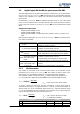
Parameter Setting
No. Description Min. Max. Fact. sett.
494 Division marks speed sensor 2 1 8192 1024