
Operation Manual

1717
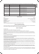
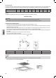
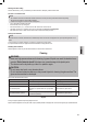
A (mm) B (mm) L (mm) W (mm) H (mm) D (mm) X (mm)
560
+4
490
+4
590 520 60 56 min. 50
• Thecutsurfacesmustbesealedwithaspecialheat-resistantlacquer,silicone,orcastingresintopreventexpansionoftheworktopthroughmois-
ture.
• Placethestovetopwiththeglasssideontoanevensurface.Avoidscratches!Placeacushionedsupportbeneathit.
• Havethepowercableconnectedtotheappliancebyaspecialistasdescribedunder
Electrical connection
.
• Theappliancemustbeinsertedintothecut-outwiththecontrolpaneltowardsthefront.Ensurethatthedistancestothecut-outarethesameon
all four sides.
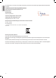
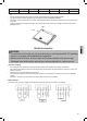
• Fastenthesuppliedclampstotherightandtheleftontheundersideofthestovetopwiththescrews(see
Fig. 3
).Insertthestovetopintothe
prefabricated cut-out.
Fig. 3
Electrical connection
WARNING:
• Theconnectiontothemainsmayonlybeperformedbyanauthorizedspecialist.Theinstallation
must be in accordance with the standards and regulations.
• Beforethestartofthework,alltheterminalsmustbedisconnectedfromthepowersupply.
• Adamagedmainscablemustbereplacedbyanauthorizedspecialistorcustomerservice.
Connection conditions
• Priortoconnection,ensurethatthepowersupplymatchestheinformationonthetypeplateontheundersideoftheappliance.
• Thesupplylinetotheappliancemusthaveanall-polecircuitbreakerinthepanelboardwithacontactdistanceofatleast3mm.(Fuses,circuit
breakersorcontactors).
• Theappliancemustbegroundedthroughaprotectiveground.
• Contactprotectionmustbeensured.Toincreasethesafety,agroundfaultcircuitinterrupterwithareleasecurrentof30mAmustbeinstalled
upstream.
• Connectiontoadomesticplugsocketandtheuseofmultiplesocketsorextensioncordsisprohibited.
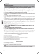
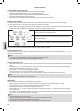
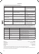
Mains connection
Thesocketmustbeconnectedtoasingle-polecircuitbreakerasdenedinthestandards.Theconnectionisshownbelow:
Clip
+1 +1