
User manual


CAUTION
CAUTIONCAUTION
CAUTION:
::
:
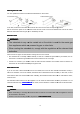
• Before mounting,
check that the wall
•
When drilling the holes in the wall always make sure that no existing electrical cables or other objects are
damaged.
•
Make sure that the vents are clear of obstacles and are not covered.
NOTE
NOTENOTE
NOTE:
::
:
Recomm
RecommRecomm
Recomm
endations for preparation work
endations for preparation workendations for preparation work
endations for preparation work
• When installing, ask another
person
•
Wear protective gloves to prevent injuries from any sharp edges.
1
11
1
2
22
2
Mounting at the wall
• The hood is mounted
at the wall or
centrally above the hob in
conformance
•
Remove the grease filter grid or aluminum grease filter (depending on the model).
• Select the fume outlet and set
the lever to the appropriate position, see “Selecting the fume outlet”.
Mounting at the wall
Mounting at the wallMounting at the wall
Mounting at the wall
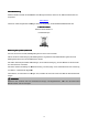
• Mark the
necessary holes for the wall mounting by using the supplied drill template and check them with a
spirit level.
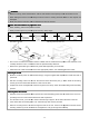
• Drill two
mounting holes Ø 8 mm into the wall and insert the dowel pins (1). Then rotate the mounting
screws (2) as far as these stick out about 4 mm from the wall.
•
Suspend the hood and tighten the screws through the hood body. Check the secure fitting and
position.
Mounting below the wall u
Mounting below the wall uMounting below the wall u
Mounting below the wall unit
nitnit
nit
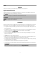
• Hold the hood
to the specified cabinet position and draw the drilling points from the inside of the unit corr
sponding to the four screw holes. Check them with a spirit level.
• For extraction mode, you
must also create a feed through of approx. Ø 130 mm in the base of the unit.
•
If the mains cable is fed through the unit, a feed through also must be provided.
•
Drill four mounting holes of Ø 4 mm through the base of the unit. Screw in the appliance with the
including washers (3) under the wall unit and tighten the nuts (4) through the hood body.
20
check that the wall
or wall unit has sufficient load capacity to
bear
When drilling the holes in the wall always make sure that no existing electrical cables or other objects are
Make sure that the vents are clear of obstacles and are not covered.
endations for preparation work
endations for preparation workendations for preparation work
endations for preparation work
person
to assist.
Wear protective gloves to prevent injuries from any sharp edges.
3
33
3
4
44
4
5
55
5
Mounting below the wall unit
at the wall or
below a suitable wall unit. Determine the
position
conformance
with the specified safety distances.
Remove the grease filter grid or aluminum grease filter (depending on the model).
the lever to the appropriate position, see “Selecting the fume outlet”.
necessary holes for the wall mounting by using the supplied drill template and check them with a
mounting holes Ø 8 mm into the wall and insert the dowel pins (1). Then rotate the mounting
screws (2) as far as these stick out about 4 mm from the wall.
Suspend the hood and tighten the screws through the hood body. Check the secure fitting and
to the specified cabinet position and draw the drilling points from the inside of the unit corr
sponding to the four screw holes. Check them with a spirit level.
must also create a feed through of approx. Ø 130 mm in the base of the unit.
If the mains cable is fed through the unit, a feed through also must be provided.
Drill four mounting holes of Ø 4 mm through the base of the unit. Screw in the appliance with the
including washers (3) under the wall unit and tighten the nuts (4) through the hood body.
bear
the extractor hood.
When drilling the holes in the wall always make sure that no existing electrical cables or other objects are
6
66
6
position
of the extractor hood
the lever to the appropriate position, see “Selecting the fume outlet”.
necessary holes for the wall mounting by using the supplied drill template and check them with a
mounting holes Ø 8 mm into the wall and insert the dowel pins (1). Then rotate the mounting
Suspend the hood and tighten the screws through the hood body. Check the secure fitting and
horizontally
to the specified cabinet position and draw the drilling points from the inside of the unit corr
e-
must also create a feed through of approx. Ø 130 mm in the base of the unit.
Drill four mounting holes of Ø 4 mm through the base of the unit. Screw in the appliance with the
screws
including washers (3) under the wall unit and tighten the nuts (4) through the hood body.