
Manual

MAINTENANCE & REPAIRINSTRUCTIONS
MAINTENANCE SCHEDULE
Perform these required maintenance procedures at the
frequency stated in the table. These procedures should also
be a part of any seasonal tune-up.
NOTE: Some maintenance procedures may require
special tools or skills. If you are unsure about
these procedures take your unit to any non-
road engine repair establishment, individual or
authorized service dealer.
WARNING: To prevent serious injury, never per-
form maintenance or repairs with unit running.
Always service and repair a cool unit. Disconnect
the spark p!ug wire to ensure that the unit can-
not start.
NOTE: Maintenance, replacement, or repair of the emis-
sion control devices and system may be performed
by any non-road engine repair establishment, indi-
vidual or authorized service dealer.
In order to assure peak performance of your engine, inspec-
tion of the engine exhaust port may be necessary after 50
hours of operation. If you notice lost RPM,poor performance
or general lack of acceleration, this service may be required. If
you feel your engine is in need of this inspection, refer service
to any non-road engine repair establishment, individual or
authorized service dealer for repair. DO rIOT attempt to per-
form this process yourself as engine damage may result from
contaminants involved in the cleaning process for the port.
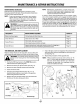
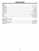
FREQUENCY MAINTENANCE REQUIRED REFER TO
Before starting engine Fill fuel tank with fresh fuel mix Page 8
Every 10 hours Clean and re-oil air filter Page 12
Every 25 hours Check and clean spark arrestor Page ! 2
Check spark plug condition and gap Page 13
I
Every 50 hours Inspect exhaust p°rt and spark arrest°r screen f°r cl°gging °r Page !2
obstruction to assure maximum performance levels
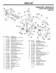
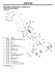
TINE REMOVAL AND REPLACEMENT
Replace all four (4) tines at the same time, because they will
wear evenly through normal use. Work on one side at a time.
WARNING: To prevent serious personal injury, 1
always wear heavy gloves when handling the l
tines. J
1. Put the On/Off Stop Control in the STOP (O) position
and disconnect the spark plug wire.
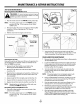
2. Remove the clevis pin clips and clevis pins (Fig. 11).
3. Remove the tines and felt washers from the shaft.
4. Clean and oil the shaft.
5. The tines are stamped with the letter "R" or "L" to
identified their position on each side of the gearbox
when facing the front of the unit.
6. Replace the tines and felt washers onto the shaft with
the hubs on the tines facing each other.
Clevis Pin_
Fig. 11
Washer
Tine Hubs
Clevis Pin Clip
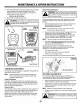
7. Ensure the tips on tines are aligned in the same direction
with each other before reinstalling the clevis pins and
pin clips (Fig. !2),
8. Repeat this procedure on the opposite side.
NOTE: When installed correctly, there will be an "R"
and !It" tine on both the gearbox and the tips of
the tines. These letters will line up in the same
direction for each side. It is important that the
tines are installed correctly.
Felt
Cushion
L
Shaft
R
L
11
m
m