® Operator's Manual Since it began making garden tools in 1850,Bolens has been known for longlasting, dependable products. Bolens eventually carried that hard.working hedtage into the outdoor power equipment industry, when it designed and built the first-ever power-driven garden tractor. Today,homeowners around the country rely on Bolens for durable, reliable power equipment at an affordable price.
INTRODUCTION THANKYOU TABLE OF CONTENTS Thank you for buying this quality product. This modern outdoor power tool will provide many hours of useful service. You will find it to be a great labor-saving device. This operator's manual provides you with easy-to-understand operating instructions. Read the whole manual and follow all the instructions to keep your new outdoor power tool in top operating condition. Service Information ................................... Rules for Safe Operation ..............
RULES FOR SAFEOPERATION NOTE: For users on U.S. Forest Land and in the states of California, Maine, Oregon, and Washington. All U.S. Forest Land and the state of California (Public Resources Codes 4442 and 4443), Oregon, and Washington require by law that certain internal combustion engines operated on forest brush and/or grass-covered areas be equipped with a spark arrestor, maintained in effective working order, or the engine be constructed, equipped, and maintained for the prevention of fire.
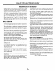
RULES FOR SAFEOPERATION • IMPORTANT SAFETY INFORMATION • • Always stop the engine and allow it to cool before filling the fuel tank. Never remove the cap of the fuel tank. or add fuel when the engine is hot. Never operate the unit without the fuel cap securely m place. Loosen the fuel tank cap slowly to relieve any pressure in the tank • Keep hands, face and feet at a distance from all moving parts. Do not touch or try to stop the tines when they are rotating. Do not operate without guards in place.
RULES SAFETY AND INTERNATIONAL FOR SAFEOPERATION SYMBOLS This operator's manual describes safety and international symbols and pictographs that may appear on this product. Readthe operator's manual for complete safety, assembly, operating and maintenance and repair information. SYMBOL MEANING SYMBOL MEANING • ONIOFF STOP CONTROL Indicates danger, warning or caution. • SAFETY ALERT SYMBOL with other May be used in conjunction symbols or pictographs.
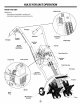
RULES FOR SAFEOPERATION KNOW YOUR UNIT STOP/OFF (0) Application: \ • Cultivating sod and light to medium soil • Cultivating in garden areas, around trees, etc. Handgrip Handlebar Handgrip On/Off Stop Control Throttle Control START/ON (I) Handlebar Knob / Throttle Cable and Switch Wires FuelCap Starter Rope Grip Primer Bulb Handlebar Knob Choke Control Shaft Tube Grip Tine Guard Air Filter/ __ Gearbox \ Muffler Spark Plug Wheel Bracket Assembly / / _Tines / 6
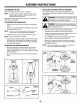
ASSEMBLY ASSEMBLING INSTALLING THE WHEEL BRACKET ASSEMBLY THE UNIT Before operating, NOTE: position You may also need to reposition height before using the cultivator. Adjusting Tine Depth section. POSITIONING If the wheel bracket assembly is not installed, or if you ever need to remove or reinstall it, follow the ensuing instructions. the unit's handlebars. Begin by carefully unpacking that nothing is damaged. 1.
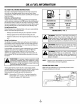
OIL & FUELINFORMATION OIL AND FUEL MIXING INSTRUCTIONS Old and/or improperly mixed fuel are the main reasons for the unit not running properly. Be sure to use fresh, clean unleaded fuel. Follow the instructions carefully for the proper fuel/oil mixture. Definition of Blended Fuels Today's fuels are often a blend of gasoline and oxygenates such as ethanol, methanol, or MTBE (ether). Alcohol-blended fuel absorbs water. As little as I% water in the fuel can make fuel and oil separate.
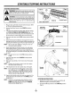
STARTING/STOPPING INSTRUCTIONS STARTING INSTRUCTIONS WARNING: Operate this unit only in a well- yen- 1 tilated outdoor area. Carbon monoxide exhaust I fumes can be lethal in a confined area. J WARNING: Avoid accidental starting. Make sure you are in th e starting position when pulling the starter rope (Fig. 8). To avoid serious injury, the operator and unit must bein a stab!e position while starting. 1. Mix gas with oil. Fill fuel tank with fuel/oil to Oil and Fuel Mixing Instructions. mixture.
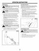
OPERATING INSTRUCTIONS OPERATING TIPS ADJUSTING Tine adjustment will vary depending on the type of soil being cultivated and how it will be used. Generally, adjusting the tines to break the soil 4 to 6 inches is recommended for most WARNING: Always wear eye, hearing, foot and 1 body protection to reduce the risk. of injury I when operating 1. TINE DEPTH this unit. gardens. Adjust the tines as follows: Move the cultivator to the work area prior to starting the engine.
MAINTENANCE & REPAIRINSTRUCTIONS MAINTENANCE SCHEDULE NOTE: Perform these required maintenance procedures at the frequency stated in the table. These procedures should also be a part of any seasonal tune-up. NOTE: Maintenance, replacement, or repair of the emission control devices and system may be performed by any non-road engine repair establishment, individual or authorized service dealer.
MAINTENANCE & REPAIRINSTRUCTIONS AIR FILTER MAINTENANCE Removing the Air Filter/Muffler Cover before you c ean or service t. 1. Place the choke control in the PARTIAL choke position (B). NOTE: 2, 3. The choke control must be in the PARTIAL choke position (B) (Fig. 13) to remove the air filter/ muffler cover. Air Filter i] / ii II II II Inside Muffler Remove the four (4) screws securing the air filter/muffler cover (Fig. 13). Use a flat blade or # T20 Torx bit screwdriver.
MAINTENANCE & REPAIRINSTRUCTIONS 8. 9. ! _ Place the muffler (with the exhaust gasket in place and bolts inserted), against the engine, aligning the bolt holes. Tighten the bolts to secure the muffler to the engine_ If using a torqu e wrench, torque to: Adjust Idle Speed Adjuster 1 WARNING: The unit may still run during idle speed adjustments. Wear protective clothing | and observe all safety instructions to prevent 80.90 in..Ib. (9-10.2 N,m) Reinstall the air filter/muffler cover.
MAINTENANCE & REPAIRINSTRUCTIONS TRANSPORTING Allow the engine to cool before transporting. Secure the unit while transporting. Drain the fuel tank before transporting. Tighten fuel cap before transporting. MOVING THE UNIT 4. Install a correctly gapped spark plug in the cylinder head. Tighten by turning the 5/8 in. socket clockwise until snug. 1. Allow the unit to cool before moving. If using a torque wrench torque to: 110-120 in..Ib. (12.3,13.5 N,m) 2. Loosen the knobs on the handlebar. 3.
TROUBLESHOOTING ENGINE WILL NOT START CAUSE ACTION On/Off Stop Control in the STOP position Turn the OnlOff Stop Control to START Empty fuel tank Fill fuel tank Primer bulb wasn't pressed enough Press primer bulb fully and slowly I 0 times Engine flooded Use starting Old or improperly Drain fuel tank I Add fresh fuel mixture mixed fuel procedure with choke control Fouled spark plug Replace or clean the spark plug Plugged spark arrestor Clean or replace spark arrestor in RUN ENGINE WILL NO
SPECIFICATIONS ENGINE Engine Type ...................................................................................................................................................................................... Air-Cooled, 2-Cycle Displacement ............................................................................................................................................................................................................. 31 cc Idle Speed RPM...................................
EPA Emission Control Warranty Statement Your Warranty Rights and Obligations The Environmental Protection Agency and Troy-Bilt LLC are pleased to explain the emission control system warranty on your 2002 and later small off-road engine. New small off-road engines must be designed, built and equipped to meet stringent antismog standards.
ENGINE PARTS - MODEL BL410 2-CYCLE GAS CULTIVATOR 21BK410G163 \ \ Item 1 Part No.
BOOM AND CULTIVATOR PARTS - MODEL BL410 2-CYCLE GAS CULTIVATOR 21 BK410G163 ® I_ 1 2 3 4 5 6 7 8 9 10 11 12 13 14 15 16 17 18 19 20 21 22 23 24 25 26 27 28 29 Part No.
MANUFACTURER'SLIMITEDWARRANTYFOR: ii!i I --SINCE-|850_ The limited warranty set forth below is given by Troy-Bilt LLC with respect with new merchandise purchased and used in the United States, its possessions and territories. Troy-Bilt warrants this product against defects in material and workmanship for a period of two (2) years commencing on the date of original purchase and will, at its option, repair or replace, free of charge, any part found to be defective in material or workmanship.