Power Vector Amplifiers V35, V60, V100, V150, & V250 Models Installation and Use Manual © 2004 Bogen Communications, Inc. All rights reserved. Specifications subject to change without notice.
Notice IMPORTANT Every effort was made to ensure that the information in this guide was complete and accurate at the time of printing. However, information is subject to change. Important Safety Information WARNING: To Reduce The Risk of Fire Or Electric Shock, Do Not Expose This Apparatus To Rain Or Moisture. Always follow these basic safety precautions when installing and using the unit: 1. 2. 3. 4. 5. 6. 7. 8. 9. 10. 11. 12. 13. Read these instructions. Keep these instructions. Heed all warnings.
Contents Page PANEL DESCRIPTIONS..................................................................................................2-3 Power Vector Front Panel..................................................................................................................2 Power Vector Rear Panel ..................................................................................................................3 INSTALLATION .....................................................................................
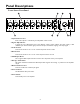
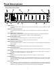
Panel Descriptions Power Vector Front Panel 1. Input Volume Control Each of the 8 inputs is controlled by an independent volume control. 2. Signal / Clip Indicator A single two-color LED located above each channel’s volume control indicates the audio activity of that channel’s input. Green indicates signal present at the input; red indicates clipping of the input signal. 3. Treble Control Controls the amount of cut or boost of treble frequencies above 10 kHz. 4.
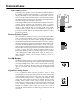
Panel Descriptions Power Vector Rear Panel 1. AC Receptacle A grounded, unswitched AC convenience receptacle with a 500W maximum capacity is provided for external equipment. 2. AC Line Cord and Circuit Breaker A grounded, 3-wire AC line cord provides power to the amplifier and is protected by a resettable circuit breaker. 3. Trans Output / Direct Out Selector Allows selection of either transformer-coupled outputs (70V, 25V, and 8-ohm) or a direct low-impedance (4-ohm minimum) output.
Installation Package Contents • Power Vector Amplifier • Switch Lock • Instruction Manual • Module Covers (8) • 12 mm Module Cover Screws (16) Ventilation and Mounting Models V250 and V150 When rack or table mounting models V250 and V150, allow a minimum clearance of 1-1/4" on the left side of the unit for proper ventilation of the fan exhaust and a minimum top and bottom clearance of 1/2". The right side has no specific clearance requirement.
Modules Output Modules Functionality The Power Vector series of amplifiers accepts Bogen signal-processing output modules, which offer a cost effective and convenient way to add specific signal-processing capability into a system. When an output module is installed, the mix bus signal is automatically rerouted through the output module, whose capabilities further process the signal before it is presented to the power amplifier section.
Connections Speakers Transformer-Coupled Speaker Connections Transformer-coupled, constant voltage speaker loads are connected to their respective load type (i.e., 70V speakers to the 70V terminal, 25V speakers to the 25V terminals) and the COM terminal. Make sure the selector switch is in the TRANS OUT position. A separate 8-ohm terminal is provided to drive 8-ohm (low-impedance) speakers through an output transformer tap.
Connections COM and GND Terminals A shorting jumper typically connects the COM and GND terminals of the amplifier together. The COM terminal is a common lead from the output transformer. For the transformer-coupled speaker output to work, one of the speaker load leads must be connected to this terminal. The GND terminal is a connection to the system’s electrical ground and used when driving loads in the Direct Out mode.
Mute Control Each priority bus (High, Medium, and Low) can be externally activated. This allows priority buses of two or more Power Vector units to be linked together for system expansion purposes. A particular mute priority can be externally forced by shorting that priority’s bus terminal to the C terminal of the Mute Control (the C terminal is the system ground). Forcing the H priority bus this way will mute all modules except for modules set for priority level 1 (highest priority).
Operation Front Panel Controls & Indicators Input Volume Controls Each input module may be individually controlled by its corresponding volume control knob. Signal / Clip Indicator A single LED located above each channel’s volume control indicates the audio activity of that channel’s input. Green indicates signal present at the input. Red indicates that the input signal coming from the input module into the amp is clipping and distorted.
Operation Rear Panel Controls Load Selector Switch A large slide switch above the amplifier’s output barrier strip determines transformer-coupled or direct output operation. The setting of this switch controls which amplifier output terminals are active and what type of filter shape will be used for the bass control. See the connections section for more information about the load selector switch. A removable switch lock is provided with the amplifier to prevent accidental changes in switch position.
Block Diagram 11
Specifications Power Output (RMS): Rated: Typical @ 1 kHz:* V35 35W 45W Frequency Response Transformer: Direct: 45 Hz to 20 kHz; +0/-2 dB 20 Hz to 20 kHz; +0/-1 dB Distortion Transformer: Direct: V60 60W 85W V100 V150 V250 100W 150W 250W 140W 200W 340W < 0.5%** < 0.1%** (.
Troubleshooting PROBLEM NO SOUND DISTORTED SOUND POOR LOW FREQ. RESPONSE (NO BASS) NOISE/HUM CONDITION CAUSE Power Indicator LED is off. • Amplifier not plugged in. • AC outlet dead. • Power switch off. • Circuit breaker tripped. Power Indicator LED is red. Input Signal / Clip LED is off. • No signal from source. • Module not installed correctly. Power Indicator LED is red. Input Signal / Clip LED is green. LED Output Meter is off. • Master or input channel volume control turned down.
Limited Warranty The Bogen Power Vector Amplifiers are warranted to be free from defects in material and workmanship for three (3) years from the date of sale to the original purchaser.