Lucent Technologies Bell Labs Innovations Multiple Digital Message Unit Installation and Use Manual Issue 1, October 1999 © 1999 Bogen Communications, Inc. All rights reserved.
© 1999 Bogen Communications, Inc. All Rights Reserved. Printed in U.S.A. Repairs to this equipment, other than routine repairs, can be made only by the manufacturer or its authorized agents. Notice If the equipment causes harm to the telephone network, the local telephone company may temporarily discontinue your service and, if possible, notify you in advance. If advance notice is not practical, you will be notified as soon as possible.
Table of Contents Introduction 1 Before You Start 1 Installation Steps 2 Power Up System 6 Front Panel Operation 7 ■ Controls and Indicators 7 ■ Recording Messages 7 ■ Listening to Recorded Messages 9 ■ Playing Messages 10 ■ Playing Messages in Sequence 11 ■ Adding a Time Delay Between Message Plays 12 ■ Clearing a Message Sequence 13 ■ Checking Message Times 14 ■ Reset Delay Times to Default 15 ■ Audio and Memory Tests Audio Test Memory Test 15 15 16 Telephone Access Operatio
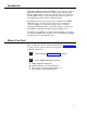
Introduction The Multiple Digital Messaging Unit (MDMU) is a micro processor based digital voice announcement system. It outputs prerecorded messages through a public address system. Up to 99 messages can be placed in the units digital memory for queued replay. Up to eight messages can be programmed to play in sequence with timed delays. Depending on the amount of memory option configured in the MDMU, multiple messages can range from 32 seconds up to 8 minutes 44 seconds in length.
3 Have Required Tools The following tools are required for the installation of the MDMU hardware an cabling.
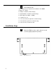
Figure 2. Rack Mounted MDMU 2 Connect the MDMU to the Telephone System AUX.
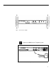
3 Plug the modular cord into connector J1 on MDMU and connect the wires on the other end to the Over Ride terminal. Figure 4. MDMU Connection to Over Ride 4 NOTE: For specific pin-out information for this connector refer to Figure 9 at the end of this guide. Messages 1 through 6 correspond to message starts 1 through 6. Connect the RJ-21 cable/connector to the MDMU Aux. Interface and to terminal block. AUX.
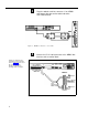
5 NOTE: Switches 1, 2, and 3 sets the number of messages in a single queue sequence. The timing between those messages is set by switches 4, 5, and 6. Switch 7 sets the total possible number of messages for the unit. Switch 8 is always in the ON position. REM Set the MDMU options on the DIP switch. Refer to the table below. BATTERY OFF ON OPTION SWITCH Figure 6 Set MDMU Options on DIP Switch Table 1.
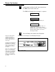
Power Up System 1 Plug the power cord into the A.C. input connector on the MDMU, then into the wall oulet. The MDMU will display three messages in sequence: MDMU 2.00 Software version of unit. 3.16 Total time available in memory for recording. IDLE Indicates the status MDMU: Idle = no activity; PLY = A message is being played out through connector J1; Delay = the time delay between successive messages is active.
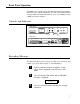
Front Panel Operation The MDMU can record messages input from the front panel through the Hand Set, Tape, and Mic connectors. The unit also record and store messages input remotely through telephone access to the REM port using a DTMF (touch tone) telephone. Controls and Indicators FRONT VIEW FUNC MULTIPLE DIGITAL MESSAGING UNIT HAND SET RUN TAPE MIC TAPE INPUT MIC INPUT IDLE FUNCTION DISPLAY RUN FUNCTION BUTTON FUNCTION SELECTION BUTTON HANDSET INPUT REAR VIEW AUX.
NOTE: Depending on number of messages optioned during installation (switch 7), the (available message numbers will read 1 through 9, or 01 through 99. 4 5 NOTE: If the message number selected has been pre-recorded, a messaged will display "SURE?" Press "RUN" again to append to the existing message. To record on another message number, press the FUNC key until the desired message number appears. Press the RUN button and begin speaking into the handset, microphone, or press play on the tape player.
Listening to Recorded Messages 1 NOTE: Use the front panel handset to listen to messages. Press the FUNC button until the display indicates monitor. MONITOR 2 Press the RUN button to select the message number. MSG-01 3 Press the FUNC key until the desired message number appears. MSG-11 4 As the message plays into the handset, the display counts down the message time. Press RUN to listen to the message. mm:ss Length of message. DONE Done playing message.
Playing Messages Once messages have been recorded, they may be played over the paging system as described below. Messages can also be queued by a contact closure of one of the switch cable pair of the RJ-21 cable (See figure 5). 1 Press the FUNC button until PLAY is displayed. PLAY 2 Press the RUN button. MSG-01 The first message is displayed. 3 Press the FUNC button to select a message other than MSG-01 to play in. MSG-09 4 Press RUN to play the message.
Playing Messages in Sequence A group or sequence of messages can be played to the output channel. The maximum number of messages in a sequence can be up to 8 (determined by the DIP switch settings on the back panel). To add messages to the sequence simply repeat the PLAY command, selecting the message to be added each time. 1 Press the FUNC button until PLAY is displayed. PLAY 2 Press the RUN button. MSG-01 The first message is displayed.
Adding a Time Delay Between Message Plays A time delay can be inserted before successive message plays. The amount of time depends on the maximum time delay set on the option DIP switch. 1 Press the FUNC button until DELAY appears. DELAY 2 Press the RUN button to display the message numbers. MSG-01 3 NOTE: A delay may only be selected for a message which has previously been recorded. Press the FUNC button to select the message number to add the delay.
Clearing a Message Sequence The message sequence can be cleared leaving the individual messages to be played separately. 1 Press the FUNC button until PLAY is displayed PLAY 2 Press the RUN button. MSG-01 3 Press the FUNC button until the following message is displayed. MSG-00 This is the message abort number. 4 Press RUN to clear the message sequence.
Checking Message Times The TIME function displays the time used for each message recorded. It also displays the remaining time available in system memory to record other messages. 1 Press the FUNC button until TIME appears. TIME 2 Press the RUN button (once) to view message numbers and recording time. MSG-01 Message number. mm:ss Time used to record message in minutes and seconds.
Reset Delay Times to Default The INIT (initialize) function resets the operating parameters and delay time to the default setting of five seconds without effecting the recorded messages. 1 Press the FUNC button until INIT appears. INIT 2 Press the RUN button. SURE ? Verification of command. 3 Press the RUN button again to initialize. WAIT DONE Audio and Memory Tests Two diagnostics tests are built into the MDMU internal software. The audio test plays a 1000 Hz tone to the installed J1 output line.
4 Press the FUNC button to end the continuous audio test. WAIT IDLE Memory Test 1 Press the FUNC button until TEST appears. TEST 2 Press the RUN button to display the test options. AUD TEST 3 Press the FUNC button to select the memory test. MEM TEST 4 Press the RUN button to initialize the test. SURE ? Verification of memory test command. CAUTION! The memory test will erase all recorded and stored messages. 5 Press the Run button again to begin the test.
Telephone Access Operation The MDMU may be accessed remotely using a DTMF (Touch Tone) telephone. Telephone access can be made directly through a telephone switching system with one of its analog stations connected to the MDMU REM port. Recording Messages 1 2 3 4 Dial the telephone extension of the MDMU. Press ✽ 7 (R for record) and the message number. (for example, ✽ 76 - record message number 6) When you hear the beep, begin recording the message.
Playing Messages 1 2 Dial the telephone extension of the MDMU. Dial the message number to play over the public address system (for example, 14, for message number 14). The message is played and added to the sequence of messages playing. Press the # key to disconnect from the MDMU. Clearing a Message Sequence 1 Dial the telephone extension of the MDMU. 2 Press 0 (or 00 if set for 99 messages).
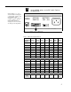
Specifications Table 2 lists the specifications for the Multiple Digital Messaging Unit. Figure 9 on the next page give the Aux. Connector pin-out definitions. Table 2 Multiple Digital Messaging Unit Specifications. Power Supply ■ Dimensions and Weight ■ ■ ■ ■ Fuse Ratings ■ ■ 115 VAC, 60 Hz, or 220 VAC, 50 Hz (specified on MDMU rear panel). Height: 1.75 inches (4.4 cm). Width: 16.25 inches (41cm) without brackets, 19 inches (48.3 cm) with brackets attached. Depth: 9.25 inches (23.5 cm).
PIN 1 2 3 4 5 6 WIRE COLORS BLUE WHITE ORANGE WHITE GREEN WHITE BROWN WHITE SLATE WHITE BLUE RED 7 8 9 10 11 12 13 14 15 16 17 18 19 20 21 22 23 24 ORANGE GREEN BROWN SLATE BLUE ORANGE GREEN BROWN SLATE BLUE ORANGE GREEN BROWN SLATE BLUE ORANGE GREEN BROWN SLATE WHITE WHITE WHITE WHITE 25 26 27 28 29 30 31 32 33 34 35 36 37 38 39 40 41 42 43 44 45 46 47 48 49 50 WHITE RED RED RED RED RED BLACK BLACK BLACK BLACK BLACK YELLOW YELLOW YELLOW YELLOW YELLOW VIOLET VIOLET VIOLET VIOLET VIOLET Table 3 20 RE