Utility Amplifier GA6A Model Installation and Use Manual © 2004 Bogen Communications, Inc. All rights reserved. Specifications subject to change without notice.
Notice IMPORTANT Every effort was made to ensure that the information in this manual was complete and accurate at the time of printing. However, information is subject to change. Important Safety Information WARNING: To Reduce The Risk of Fire Or Electric Shock, Do Not Expose This Apparatus To Rain Or Moisture. Always follow these basic safety precautions when installing and using the unit: 1. 2. 3. 4. 5. 6. 7. 8. 9. 10. 11. 12. 13. Read these instructions. Keep these instructions. Heed all warnings.
Description The GA6A is a rugged six-watt, dual-input audio amplifier with a wide variety of smaller applications including background music, relaying communication from one room to another, or sound reinforcement. The GA6A delivers rated power at not more than 1% total harmonic distortion from 75-15,000 Hz into transformer-coupled or direct low-impedance loads. Inputs for a low-impedance balanced dynamic microphone and an auxiliary audio source (tuner, tape deck, etc.) can be mixed.
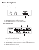
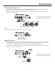
Panel Descriptions Utility Amplifier Front Panel 1. MIC Control - Regulates the level of microphone output to speakers. 2. AUX Control - Regulates the level of the AUX source to speakers. 3. Power Switch - Controls AC power to the amplifier. Illuminates when ON. Utility Amplifier Rear Panel 1. Speaker Output Barrier Strip - Output terminal strip provides for 8-ohm, 25V, and 70V speaker outputs. 2. Shorting Link - Used when 25V or 70V speakers are to be connected to the GA6A.
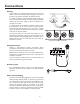
Connections 70V & 25V Speaker Systems Connect the 25V or 70V speaker loads to the corresponding terminals (25V or 70V) and the common terminal. Make sure that the total wattage of all the connected speakers is less than 6 watts. Note: Do not use both the 25V and 70V terminals at the same time. Use only one type of speaker (25V or 70V) for all speakers connected to the GA6A. Note: If using multiple speakers, check for proper phasing. See Section on Phasing.
Connections Phasing As the voltage on a speaker changes from plus to minus, the speaker cone moves from pushing out to pulling in. If you reverse the polarity, the speaker responds in the opposite manner. If a speaker is pushing out and an adjacent speaker is pulling in, some of the pressure caused by the speaker pushing out will be absorbed by the speaker pulling in. These two speakers are operating out of phase.
Operation Power The AC line cord should be plugged into a three-wire, grounded outlet providing 120V AC, 60 Hz. The power switch illuminates when unit is switched ON. MIC Control Controls the amount of MIC signal heard at the output. Clockwise increases the signal. AUX Control Controls the amount of AUX signal heard at the output. Clockwise increases the signal. Treble Control Switch Provides a stepped increase or decrease in high frequency (above 10 kHz) heard at the output.
Specifications Power Output: Frequency Response: Total Harmonic Distortion: Inputs: Sensitivity: Hum & Noise: Output Impedance: Tone: Controls: Terminations: Protection: Power Consumption: Dimensions: Shipping Weight: 6 watts RMS 30 Hz - 12 kHz +0 dB, -3 dB Less than 1% at rated output power Lo-Z MIC, balanced; AUX MIC 0.3 mV; AUX 0.