
Details for Connecting Two SC-2030 Controllers with TM-2030

How to use the TM-2030 to control two SC-2030 Solar chargers to control up to
62 amps from solar panels in a 12 or 24V battery system.
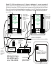
You can't just parallel the solar inputs of the SC-2030 and connect 60 amps from panels, because the current won't properly
divide between the two. Therefore when using two SC-2030’s, the solar panels should be separated into two roughly equal
groups, with a separate pair of wires for each group going to the inputs of two separate SC-2030's. However the outputs from
each SC-2030 to the batteries can be paralleled in the obvious way: + to + and minus to minus .This is illustrated on the next
page.
The two SC-2030 Solar Chargers are slightly different: one will be identified as Unit 1 and the other Unit 2. They will be
distinguished because Unit 2 has an identifying jumper (see kit below) that needs to be plugged into connector J6 on the rear
of the unit. The temperature sensor should be connected to the SC-2030 Unit 1, without the jumper. Temperature
information from the Unit 2 SC-2030 will be ignored.
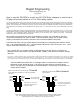
yellow
green
red
black
yellow
green
red
black
Hold two RJ-14 connectors
from each end together of 4
wire phone cable.
Hold two RJ-14 connectors
from each end together of 4
wire phone cable.
yellow
green
red
black
black
red
green
yellow
Make or purchase one (usually longer) Crossed
phone cable from TM-2030 to 3 way phone adapter
connector.
Make two (usually shorter) Non-crossed
phone cables.
As shown on wiring diagram, three communication cables from TM2030 to SC2030’s are required. Two of the two cables
need to be “non crossed” as described below, and are usually short. One of these is connected to each of the SC-2030's,
with the other end connected to the 3 way modular triplex adapter--thus occupying two of the three positions on the adapter.
not necessarily the
colors shown here
Bogart Engineering
www.bogartengineering.com
07/31/2017
These views show facing the sides of the connectors that do not have the plastic retainer
clip. Commercially modular cables used to usually be made "crossed", but recently
there seems to be no consistency to the way they are made.
When these are wired as shown on the wiring diagram on page 2, you will be able to see solar
current (SOL) separately from each SC-2030. To access the SOL display, the SC-2030 must be
properly connected to the Trimetric, and solar current must be available to the panels.
Press and hold select until you see AH appear in the display, then repeatedly press select to access
SOL. This should appear after “rPC”. The SOL display will show the solar current from unit 1. Press
reset to show solar current from unit 2 (S02).
The “crossed” and “non-crossed” cables are distinguished by the way the two connectors are
attached at each end as shown in the diagram below. Polarity of the connectors must be carefully
observed.
A kit is available that contains two 3.5 ft straight cables, one triplex phone adapter, and one
identifying jumper referred to above. The third longer cable must be crossed as shown
below. This goes from the TM-2030 to the phone adapter. Verify polarity if purchasing from
another store or retailer.