
Instruction Manual

To Solar array and
controller
Inverter and
loads for
battery
system 1
Shunt that measures inverter
load (or charging) current.
Pentametric
display device
(optional)
Pentametric
computer
interface
(optional)
to RS232
computer port
Temperature
sensor
4 connectors
Pentametric
input unit
4 wires (2 twisted
pairs) up to 1000 ft
Shunt that measures battery
system 2 net current
Shunt that measures battery
system 1 net current
Fuseholders with
2 A fuse
All loads and all
charging sources for
battery system 2.
To Wind generator and
controller
12 to 48 VOLT
BATTERY
SYSTEM #1
12 to 48 VOLT
BATTERY
SYSTEM #1
12 to 48 VOLT
BATTERY
SYSTEM #2.
12 to 48 VOLT
BATTERY
SYSTEM #2.
SHUNT: 50 MV/500 AMP
OR 100 MV/100 AMP
SHUNT: 50 MV/500 AMP
OR 100 MV/100 AMP
SHUNT: 50 MV/500 AMP
OR 100 MV/100 AMP
SHUNT: 50 MV/500 AMP
OR 100 MV/100 AMP
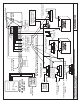
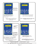
FIGURE 1: PENTAMETRIC TYPICAL BATTERY MONITOR CONNECTIONS. Shows some possible locations for shunts.
A maximum of 3 can be used with one PentaMetric
FIGURE 1: PENTAMETRIC TYPICAL BATTERY MONITOR CONNECTIONS. Shows some possible locations for shunts.
A maximum of 3 can be used with one PentaMetric
BOGART ENGINEERING 7/21/08
+
+
+
+
_
_
_
_
Shunt that measures
solar array current.
Shunt that measures wind
generator current.
relay coil
controlled by
PentaMetric
SHUNT: 50 MV/500 AMP
OR 100 MV/100 AMP
Kelvin terminals
-
-
-
-
-
-
-
+
+
+
+
+
+
+
+
+
-
+
AMPS 1
AMPS 2
COMMON
VOLTS 1
VOLTS 2
AMPS 3
-
To the Kelvin terminals
of up to 3 shunts max,
to measure amps1, 2
and 3.
SHUNT 1
SHUNT 5
SHUNT 2
SHUNT 3
SHUNT 4
SYSTEM
GROUND IF
USED.
SYSTEM
GROUND IF
USED.
IMPORTANT: This shows 5 possible locations for shunts:
however the PentaMetric can only use 3 of these at one time.