
Instruction Manual
6
Section 1: Overview of PentaMetric capability.
1.A: PentaMetric system general capability
The PentaMetric battery system monitor provides comprehensive and flexible battery monitoring for a
variety of different types of battery systems which are charged by solar, wind or generators. It is
intended to be most useful for systems which are regularly charged and partially discharged, rather
than backup power systems that are only rarely called upon to be discharged, such as uninterruptible
power systems (UPS). The system can monitor up to two battery banks simultaneously with a
common negative connection. A typical application would be to monitor a lead acid battery system
with capacity of from 10 to 10000 amp hours, with system voltage from 12 to 48 volts, with one or
more charging systems, such as a solar array, wind power, or generator system, and which is partially
discharged daily by loads powered through an inverter. Its purpose is to provide the user with
information necessary to check that the batteries and charging system are operating correctly, to keep
users informed about how much energy is in the battery system at any time, and. to anticipate and
identify problems before they cause a loss of service.
1.B: System components and interconnections.
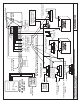
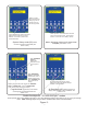
Refer to figure 1. Information on the battery system is gathered and processed by the PentaMetric
input unit which is located near the batteries and shunts. There are two ways to access and control
the data which it collects. The data can be read, and alarm setpoints and other control parameters can
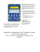
be controlled by a separate PentaMetric display unit (figure 2) which has an LCD display and push
button controls. Alternatively a computer using software (for Windows operating system) and a
PentaMetric computer interface connected to its RS232 I/O port can access and control the data.
Both the display unit and computer interface may be used simultaneously. Or, the input unit may
run by itself most of the time, gathering data, but only connected to the readout unit or computer when
data needs to be read. Both connect to the input unit by a 4 wire power and communications cable
which may be as far as 1000 feet away from the input unit.
1.B.1: The PentaMetric input unit (PM-5000-U)
The PentaMetric input unit senses data from the battery system. The PentaMetric input unit (5.5
x 4.25 x1.75 inches), is located near the battery system. It has four plug in connectors, one of
which has 9 wires that sense data (from current shunts, and from the batteries) and supply power
to the PentaMetric. These wires monitor up to 3 channels of current (amperes), and 2 channels of
“volts”. Another RJ11 connector attaches a temperature sensor. From these data all the other
readable data are derived. A third connector can control a relay for starting a generator or
providing an alarm of low or high battery level. Another connector supplies 4 wires (up to 1000 ft
long) that connect to the readout unit and/or the computer interface. The input unit also internally
processes the data to produce “derived” information such as watts, watt hours, amp hours, battery
% full, etc, which may be viewed by the display unit or by computer access. The input unit also
logs data, such as daily amp hours and watt hours, charge cycle discharge information, and
records battery efficiency data to allow analysis to determine if the system is operating as
expected. Logged data may be viewed from the display unit however it is most conveniently
viewed using the computer interface.