
Instruction Manual

18
4. Run 4 wire cable from input unit to PentaMetric display unit (if used) and the computer interface (if
used.) Cable requirements: We recommend twisted pair wire, such as Cat5 cable. For a short
run (less than 50 feet) probably any 4 wire cable will be OK. For longer runs use twisted pair wire
with minimum size wires of AWG#24 up to 600 ft, or AWG#22 up to 1000 ft. If more convenient you
may wire the computer interface to the display unit, then wire either of these to the input unit.
Remove or obtain the 4 wire connector that plugs into the input unit. If using twisted pair wires
one twisted pair should be used for the left two terminals and another twisted pair should
be used for the right two terminals. The wires should be connected in this sequence: The wire
going to the “left” terminal (looking from the wire entry side) on the plug in connector
should go the left terminal (also looking from the wire entry side) of the display unit.
Likewise for the computer interface. The remaining three wires should be connected to the
terminals in the same left to right sequence. For further guidance look at the markings on the circuit
board identifying the terminals: “4, 3, +, -“. When using twisted pair it’s important that 4,3 be on
one pair. Before plugging it in to the input unit, check wires for correct order on all devices again.
Then plug in the 4 terminal connector to the input unit.
5. Before applying power by inserting the 9 pin connector, check the wires from shunts and
battery(s) connector as described in caution just above step 1. Then plug in 9 terminal
connector. The backlight of the LCD display on the input unit should light up.
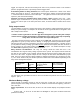
6. Cursory check of operation: Using program modes P11, P12 and P13 (refer to section 6.A under
P11,P12,P13 ) set the correct shunt types for channels 1, 2 and 3. See that the “volts” and “amps”
readings are reasonable, which establishes that the wiring is OK. With 0 current in any given shunt,
the “amp” display corresponding to it should show 0.0 or 0.1 at most. (But remember that the
PentaMetric takes some current too, which will be measured by the “Shunt 1” in Figure 1.) Load
currents (from turning on a load such as a light) should cause amp values to become more
negative. Charging currents should cause amp values to become more positive.
Section 3B Choosing and installing program parameters for your application
If you are using the PentaMetric Display unit, decide what display items you want to easily
select by the 5 “data select” switches. You can allocate from 1 to 5 display items to each of the
5 switches. Keeping a smaller number will provide simpler operation. If an item only very rarely
needs to be observed, the “all display” mode option can always be used--it can access all the displays,
but at the cost of a lot of button pushing to get there. Allocation to display items to particular switches
is accomplished by program modes P1-P5. Refer to programming section 6.A under P1-P5 for details
on how to do this.
A paper label identifying your choices for each switch which fits in the pocket of the PentaMetric
display may be made by visiting the bogartengineering.com website and downloading a Word file
called: “PentaMetric Label template”. Then modify the text using the Microsoft “Word” program
according to the switch allocations you have decided upon, and print it. Instructions are in that file.
Finally, for each display option you have chosen, above, refer to its detailed display description, in
Section 6.B. Each program mode that affects that display option is listed there. Then for each such
program mode check Section 6.A for how to set the correct programmed data to insure that the
display will show correct data.
Section 4: User’s instructions for display unit.
4.A: Refer to figures 2 and 3. There are five display modes. These are selected by “other
displays” switch: Most of the time it will be in the “5 switch” display mode which
allows the commonly used data to be accessed by the top row of 5 switches and also
gives the user access to the alarms when they occur. The other 4 modes are used
more occasionally for special purposes.
The quickest way to understand these is to refer to Figures 2 and 3. Then read text below
(Section 4.A.1 through 5) for complete description if necessary.