
Instruction Manual

17
Section 3: Installation of PentaMetric
Section 3A. Hardware installation (wiring) instructions
SAFETY WARNING
Only a qualified person who understands electrical safety procedures should
install the shunts and meter. Batteries if accidentally shorted can cause
intense heat. Systems with greater than 35 volts can present shock hazards.
CAUTION: To prevent possibly severe damage to the PentaMetric input unit,
BEFORE APPLYING POWER BY CONNECTING THE 9 PIN GREEN
CONNECTOR, (step 5 below) pay particular attention to the following:
All shunts must be located in the negative side of the battery system. One
way to verify this, and also insure that a wiring error will not result in a puff of
smoke coming from your PentaMetric, before plugging in the 9 pin green
connector, perform the following test using a multimeter: With multimeter set
to read “volts”, first connect the negative probe to pin 1 of green connector
(See figure 4). Then check the voltage (using the positive lead) checking each
pin from 3 through 9. Be sure that the voltage at pins 4 through 9 are all near 0
(less than 0.1 volts) The ONLY pins that it is OK to have a higher voltage
(usually battery system voltage) is at pins 2 and 3. Voltage here must be
positive, not negative.
1. It is advisable to make a drawing of the shunts and wiring to PentaMetric.
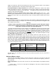
2. Disconnect DC power and install up to 3 shunts in necessary locations using large cables of the
same size as are presently used for conducting current from the batteries. As shown in figure 1
they must be placed in the negative side of the battery system such that all the current that you
wish the meter to read will pass through them. If placed in the positive side, it will not measure
properly, and may damage the meter.
3. Mount PentaMetric input unit. Remove cover of input unit. Remove (or obtain) the 9 pin connector
that plugs into the input unit. All wires from the batteries will attach to this connector. Refer to
figure 4 (Drawing of 9 pin connector) that shows how to connect the battery + and - terminals and
also all the shunts. It is of course much easier to wire while the plug is removed from the input unit.
The wire used has no special requirements.
NOTE 1: When installing the wire from the “+” end of the battery install an in line fuse (2 A fast
blow) near the “+” wire of the battery. This provides protection for the wires in case of short, and
provides an easy way to disconnect power to the PentaMetric if needed. (The reason for a “fast
blow” fuse is that it has less voltage drop, to make voltage measurements a little more accurate.)
NOTE 2: Any unused connections to shunt inputs must connect to pin 1 of the connector (battery
minus terminal).
NOTE 3 :If you are not using Battery volts 2 we suggest connecting this input to pin 2. (i.e. connect
pin 2 to pin 3) This will allow the meter to measure “Watts” and “Watt hours” on its Watts 2 or Watt-
hr 2 channel, if desired.