
Instruction Manual


14
logged, and amp-hour, watt-hour and battery% full data is to be preserved. Power is not needed to
preserve “programmed” data, or previously recorded “logged” data.
If two battery banks are being monitored, the second system should have a shunt in the “minus
battery” line shown as “shunt 4”. This should be connected to the “Amps2” channel and that battery
“+” terminal should be connected to the Volts2 input.. No significant current is taken from the “volts2”
input wire. (less than 200 microamps)
Important: Connect all unneeded shunt inputs (“amps” inputs) together and to the “- volts”
terminal. Figure 4 illustrates this. If you only need to measure one voltage point, you may wish to
connect the “Volts 2” input to the same point as the volts1, so that the Watts 2 channel can be used if
desired.
Relay output control:
The PentaMetric can actuate a control relay having a DC coil with a voltage requirement equal to the
battery #1 system voltage. For example it can be used to control a generator which is designed to start
with a simple contact closure.
Warning:
If used to control a generator it must be a type that is designed to operate safely with a simple
contact closure, including mechanisms to automatically start it safely, and to keep it operating
safely when not under the control of a responsible person.
The relay coil must be wired to its own connector on the input unit. (See figure 1) The relay can be
programmed to go ON (or OFF) when the “Battery 1” voltage goes below a predetermined setpoint,
OR when the state of charge of the battery goes below a predetermined setpoint. It will then go OFF
(or ON) when the Battery 1 voltage goes above another
predetermined setpoint, OR when the state of
charge of battery #1 goes above another predetermined setpoint. For detailed description of setup
see section 6A Programming section, under P30 and P31.
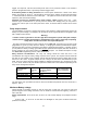
Relay technical considerations: The relay coil voltage should be rated such that it can
accommodate the range of battery voltage expected in the system. The required current should be
less than 1A. For example, a 24V “nominal” system might be expected to have a voltage that can vary
from 21.0 to 32.0 volts. A typical example of such a relay is the R10 series manufactured by Tyco/
P&B. Here are 3 relays with their ratings suitable for ambient temperatures up to 40 degrees C (104
F.) The “XXXX” shown in the part number represents numbers that can be different depending on the
relay contact arrangement required.
The K10 series from Tyco/P&B can also be used if the ambient temperature does not exceed 26 C
degrees . (80 F).
Maximum Battery voltage
Volts#1 should not normally exceed 70 volts for more than a short time. The meter is fairly well
protected against short voltage transients, such as would be encountered from lightning. Volts #2 is
OK to 100 volts.
Power requirements: 18 ma at 24 volts; 30 ma at 12 volts: without display unit (computer interface
only)l.
24 ma at 24V -- or 43 ma at 12 volts with LCD backlight on “low” (after no buttons have been
pushed for 5 minutes)
Tyco/P&B Part
number
nominal
coil volts
DC
Voltage range up to 40
C (104F) ambient
Min-Max V.
Max. coil operating
current (milliamps)
R10-XXXX-V180 12 9- 16.5 99
R10-XXXX-V700 24 18-32 50
R10-XXXX-V2.5K 48 36-61 27