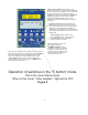
PentaMetric System Instructions Please read this first! How to use these instructions December 8, 2016 ) The PentaMetric system is complex. Because it can perform so many different functions these instructions must be extensive. Most applications will not require all of this capability. Considerable thought was given to make instructions that allow you to extract the information for the items you need, without having to read what you do not need.
Table of contents PentaMetric summary of functions.............................................................................. 5 Section 1: Overview of PentaMetric capability. .......................................................... 6 1.A: PentaMetric system general capability .............................................................................................. 6 1.B: System components and interconnections. .......................................................................................
Section 6: PentaMetric reference section. ............................................................... 22 6A. Detailed description of each program option (total 49)..................................... 22 How to access program modes with the PentaMetric Display Unit:........................................................ 22 P1-P5: Switch select;............................................................................................................................... 23 P6: “Volts1” label: ..........
6.C.1: “Periodic logged data” :................................................................................................................. 32 6.C.2: Battery discharge profile Logged Data: ........................................................................................ 33 6.C.3: System “battery efficiency cycle” logged data: ............................................................................. 34 6.D. Output control Relay programming and operation.......................................
PentaMetric summary of functions For battery systems from 12V to 48V (nominal). Measure 1 or 2 battery systems with common negative. With one battery system: battery current plus two charging sources/loads can be measured. System consists of these possible components: 1.data input unit to collect, process and log data (near batteries). Required component. 2. optional readout unit with LCD display and control buttons Connect to input unit with 4 wires up to 1000 feet away. 3.
Section 1: Overview of PentaMetric capability. 1.A: PentaMetric system general capability The PentaMetric battery system monitor provides comprehensive and flexible battery monitoring for a variety of different types of battery systems which are charged by solar, wind or generators. It is intended to be most useful for systems which are regularly charged and partially discharged, rather than backup power systems that are only rarely called upon to be discharged, such as uninterruptible power systems (UPS).
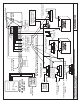
SHUNT 3 SHUNT: 50 MV/500 AMP OR 100 MV/100 AMP SHUNT: 50 MV/500 AMP OR 100 MV/100 AMP Shunt that measures wind generator current. + SHUNT 2 SHUNT: 50 MV/500 AMP OR 100 MV/100 AMP SHUNT 4 Shunt that measures inverter load (or charging) current. + Shunt that measures solar array current. + - + _ + - + AMPS 2 - + AMPS 3 Kelvin terminals To the Kelvin terminals of up to 3 shunts max, to measure amps1, 2 and 3.
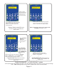
1.B.2 The PentaMetric display unit (PM-100-C) The PentaMetric display unit is designed to be customized for simple or complex systems. The display unit (see figure 2) allows observation of all parameters which the input unit measures-however most applications will require monitoring only some of these--in some cases only a small number. The display unit has a two line 16 character LCD display, and also a sounder for audible alarms.
Label for top 5 switches: Each switch can be assigned arbitrarily up to 5 display items. Assignment for each switch to the desired items is accomplished by program modes P1-P5. A card may then be printed with these items and inserted in transparent pocket of front panel. A "Word" file is available ("Pentametric Label Template") which can be modified and printed to easily produce this label on your printer. Sol amp. Batt. Amps. Sol amp-hr Sol W-hr Bat%Ful. Bat volts. Days since charged.
RIGHT and LEFT arrow switches show data going back or forward in time for the same type data. RIGHT and LEFT arrow switches access data going back or forward in time . Goes forward or back in increments of 5% battery capacity. UP and DOWN arrow switches access the different data recorded at one sample date/time. The "bottom" position is the recorded date/time. Battery discharge voltage profile logged data mode(BH) See section 4.A.
1.C: Summary of the 29 specific “real time” measurements made by the PentaMetric. These are summarized here. They are described in much more detail in section 6B. 1.C.1 Battery volts, amps, amp hours, watts, watt hours for up to 2 battery systems Measures instantaneous battery volts, amps, watts, in and out of batteries, amp hours from full charge, watt-hours, for up to 2 battery banks sharing a common negative. Volts are measured to 0.1 volts, from 10.0 to 99.9 volts. Amps are measured from .
displays. This is useful for monitoring average wind generator “amps” input, or other rapidly varying charging source. These are used for the “battery alarm” parameters, where it is not desired to sound an alarm for very short term anomalous events, and for logging of volts and amps where it would not be desirable to record a very short term event. 1.C.8Temperature This measures temperature from -20C to 65C (-4F to 150F). The TS-1 temperature sensor accessory is necessary when measuring temperature. 1.
1.F: Relay output control: It provides for control of a relay that: (1) turns “on” when the battery voltage drops below an “on” set voltage or when the state of charge of the battery decreases below an “on” setpoint. and (2) turns “off” when the battery voltage rises above an “off” set voltage, or when the state of charge of the battery exceeds an “off” setpoint This could be used to control a generator or external alarm .
logged, and amp-hour, watt-hour and battery% full data is to be preserved. Power is not needed to preserve “programmed” data, or previously recorded “logged” data. If two battery banks are being monitored, the second system should have a shunt in the “minus battery” line shown as “shunt 4”. This should be connected to the “Amps2” channel and that battery “+” terminal should be connected to the Volts2 input.. No significant current is taken from the “volts2” input wire.
38 ma at 24V -- or 70 ma at 12 volts with display unit, LCD backlight on “high” (just after pushing buttons) Cable considerations from input unit to readout control unit or computer interface. When runs exceed 50-100 feet, twisted pair cable (such as cat 5) should be used. Wire resistance for each of 4 wire cable should not exceed 30 ohms from one end to the other for the PentaMetric readout/control unit. This allows 1000 feet of length if AWG22 wire size or larger is used or #24 for up to 600 ft.
1 2 3 - 4 + 5 6 + 8 9 - that measures charging source or load (not usually a battery shunt) . Connect + and - as same as described for terminals 4-5. + SHUNT 3: Connect these two to a shunt "SHUNT 2": Connect these two to second battery shunt (or charging or load shunt). Connect + and - as same as described for terminals 4-5. - 7 FIGURE 4: PentaMetric Connections to input unit removable 9 pin connector.
Section 3: Installation of PentaMetric Section 3A. Hardware installation (wiring) instructions SAFETY WARNING Only a qualified person who understands electrical safety procedures should install the shunts and meter. Batteries if accidentally shorted can cause intense heat. Systems with greater than 35 volts can present shock hazards.
4. Run 4 wire cable from input unit to PentaMetric display unit (if used) and the computer interface (if used.) Cable requirements: We recommend twisted pair wire, such as Cat5 cable. For a short run (less than 50 feet) probably any 4 wire cable will be OK. For longer runs use twisted pair wire with minimum size wires of AWG#24 up to 600 ft, or AWG#22 up to 1000 ft. If more convenient you may wire the computer interface to the display unit, then wire either of these to the input unit.
To get to the “5 button” display mode push the “other displays” button (lower right) repeatedly until the adjacent yellow lamp goes off. Figure 2 has instructions for the switches in this mode. The four other less used display modes are accessed by pushing the “other displays” button. Figure 3 has instructions for these. For the following four modes the “other displays” light is on. They are identified by the first letters in the LCD display as follows: SH:........
4.A.2: System history display logged data mode (“SH”) You can access this data most conveniently using a “Windows” computer with the PentaMetric PMComm software. See below in this section. However the “Display unit” in this mode can also be used to access this data. Refer to figure 3 for a summary of how to navigate in this mode. The purpose of this display is to show the periodic “logged data” (such as watt hours, amp hours, temperature) as described in section 6.C.1.
be generally negative. The most interesting point to observe in this data is the voltage (and amps) at the low point of discharge, to see that this voltage was not becoming excessively low. If the battery voltage starts to go too low (compared with similar previous discharge levels in the past), this would indicate a loss of battery system capacity for some reason, such as a bad cell, or bad connection in a series string of the battery set--or just old batteries.
(3)Invoke the program (double click icon) to open a window that will allow viewing data, viewing and changing programmed data, and downloading logged data. After first opening the program choose the “options” button and choose the correct computer “com” port which you have connected to the PentaMetric. Then, close that window and select “Start display”. If everything is properly connected the green “Receiving data” should periodically appear at the bottom of the screen.
(c) After the data is changed to your liking, push the RESET(program) button again to install the new data, and to resume viewing other program data. (4) Continue or Exit: Provided that the cursor is not still flashing, (indicating you are not in the program change mode) you may use the up/down switches to observe other programmed data, or push the “OTHER DISPLAYS” button to exit this mode.
function to read “true” amp hours instead of being compensated by assumed battery self discharge, as more fully described in section 7. It will also prevent the amp hours from being automatically reset to 0, which can occur if a “capacity” value is entered which is non zero. P16: Filter time constant. Sets the filtering time for “filtered” Amps display (AD10-AD12) and filtered “volts” display AD3, AD4. Choose 0, 0.5, 2 or 8 minutes. This makes these displays respond more or less slowly.
a) P30 sets the voltage and Percent Full that will cause the relay to go ON. b) P31 sets the voltage and Percent Full that causes the relay to go OFF. c) If the ON voltage is higher than the OFF voltage, then the relay will go ON when the voltage is above the high voltage, and OFF when it is below the low setting. If you want the relay to work in the opposite sense, then put the ON voltage below the OFF voltage.
P31: RelayOff: 28.8V, Batt%=80. In case of disagreement between the voltage setting and BATT%FULL setting the voltage setting will govern. . P32-Batt1 charged criteria. This tells the PentaMetric when the battery system measured by “volts1” and “amps1” is to be declared “charged”. When this occurs, the “days since charged” display (AD24 or AD25) will be reset to zero.
P38: Day and time set. This is used to set the time and day of the PentaMetric internal clock. The “time” is set in as 24 hour time. The “date” is just an integer from 0 to 999, and can be an arbitrary number which will increase by 1 each day that elapses. (You could, if you wish, enter the “Julian” date, which is the number of days from the beginning of the year, beginning with Jan 1 as “1”.
P45: Erase periodic data. This “program” mode allows you to erase and initialize the memory for the “periodic logged data”..(Section 6.C.1) After entering this mode, note that the “RESET” lamp is lighted. If you push the RESET button, a number in the display will gradually go to “0”: CAUTION: When it gets to “0” all periodic data will be erased. This is the “amp hour”, “watt hour”, “temperature”, “volts” and “amps” data that is recorded at specified times.
These both read a “filtered” version of Battery1 volts, with a time constant which may be 0.5 minutes, 2 minutes or 8 minutes, or, (if this filtering action is not desired, it may be set to 0, in which case these displays will be identical with AD1 or AD2.) Thus it is a very “sluggish” version of Battery1 and Battery2 volts. The 8 minute time constant is the slowest, and most “sluggish”. The “.5 minute” time constant means that if the input voltage suddenly changes from 20.0 to 30.
filter time is possible-- this same number is used for ALL filtering functions, so filtered volts and filtered amps must have the same filter time applied. There is also an option for no filtering, if desired. The labels for these 3 items are determined by Program mode P7, P8 and P9. “Amps” label: see section above for AD7, AD8, AD9 for a description of these.
the second case. This is an important “bottom line” number of the battery system performance, as it is a measure of total “storage utility” gotten from the batteries. This number is periodically stored every 3 hours in “non volatile” memory, which means that if power is removed from the PentaMetric, it will only lose the last 3 hours of data at most. Program modes that affect AD7, AD8, (Amps1, Amps2), similarly affect this display. Refer to section AD7 AD8, for information about these program modes.
AD26, AD27 Days since equalized, bat1 (AD26) ,bat2 (AD27), Program modes affecting data: None This function is intended to show how many days have elapsed since the batteries were last equalized--useful for those systems that need manual equalization.
Before beginning to record you may wish to erase all the data recorded in the past using (Program number P45), although it is not necessary to do this in order to “make space” for the data. When the memory is full new data is still recorded by overwriting the oldest data. Size of memory: Data will be recorded until the memory is filled--after which the oldest data will gradually be overwritten with new data. To estimate the number of data points in the memory use the formula: First compute 61[3 + (2 p)].
6.C.3: System “battery efficiency cycle” logged data: Program modes affecting data: P14, P15, P32, P33, P47. Data always on: This type of data is “always on”--it does not need to be programmed on. . It is available either from the “display unit” using display modes AD29 through AD40 or as a downloaded file using the computer interface. The downloaded file can then be accessed on your computer using Excel, or other spreadsheet program which shows a history of previous charge cycle efficiency.
Note that a different way of measuring this could have been done by starting at the time as above described, but declaring an end at the time (after discharge and recharge) at which the battery just first met the “charged” criteria. Thus the additional charging (or gassing) of the battery that occurs after this, while the battery is pretty well charged would not be counted.
between the charge and discharge amp hours,(7)Charge efficiency, which is item 4 divided by item 5, 8)Self discharge current, which is item 6 divided by item 3, (9) Same as item 7, except averaged over some number N of cycles, and (10) Same as item 8 except averaged over some number N of cycles. The number N can be selected in the “options” box, under “Efficiency average cycles.
might want to be “noted”, for example to turn off a generator. To activate these refer to Section 6.A, under P22, P24, P32, P33. .Section 7 describes in detail how the PentaMetric senses that the batteries are charged. 6.E.3: Battery voltage high” This results in an alarm when battery 1 voltage (AD1 or AD2) is greater than “battery high” voltage setpoint or battery 1 “battery % full” (AD22 or AD23) is greater than “battery % high” setpoint. To set these, refer to Section 6.A, under P22, P24,P27, P29. 6.E.
slowly. Eventually, as the battery begins to approach full charge the voltage will rise to the “bulk voltage” setting of the charger. (This charger could be an inverter charger or solar charge controller.) The voltage is prevented from exceeding this “bulk voltage” by the charger to prevent the battery from gassing excessively.
Step 3. Typically during step 2 the battery will track state of charge closely, but not exactly because the self discharge will not be compensated precisely. Usually the recommended values will cause the “battery % full” to read slightly lower than true, thus giving a conservative view of remaining charge left in the batteries. However when the battery is again fully charged, the meter will again reset to “100%” to resynchronize the battery with the meter, and then the meter will continue as in step 2. 7.