
TM-2030 Technical Manual

4
If your system has four 6V batteries in series-parallel, or two 12V batteries in parallel, then on the
negative side of the battery system you will then have only one cable connecting two negative poles
from two different batteries connected together. Before step 2, there must be no other wires going to
inverters, grounds, solar controllers or ANYTHING ELSE connected to the negative side of the
battery system except for one cable that connects the two battery negative poles together.
We emphasize this because quite often people make the mistake of leaving chassis ground, or one
or more other device still connected to the negative side of the battery system—which will result
in the wrong battery “amps” being read on the TriMetric.
STEP 2: Reconnect all the cables you took off in STEP 1 to either of the two large bolts on the shunt. All
such cables must be connected to one side of the shunt—leaving the other bolt empty for step 3. This
doesn’t mean that they have to go directly to the bolt itself—but must connect electrically to this side of the
shunt. Arrange the shunt so the two small “Kelvin” screws on the side or top of shunt are accessible for
connecting later (Step 5).
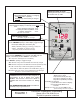
STEP 3: Obtain “shunt to battery cable” referred to in B2 above. See diagram page 7, Figure 1B,
“After cable installation”.
Connect one end of cable to the now empty large bolt on the shunt.
Connect the other end of cable to the now bare battery negative battery connection provided in STEP1.
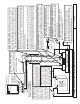
PREPARE FOR STEPS 4-6: Connecting wires from meter to battery and shunt. Refer to the
wiring diagram on the last page of these instructions to see how the wires connect from the meter to the
battery system. Every system will require a minimum of four wires shown as G1, G2, SIG +B1 shown in
table below. If you also wish to also monitor the voltage (only) of a secondary battery you will also need
to connect a fifth wire from the positive post of this battery to meter as shown in wiring diagram.
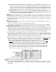
The terminal block on the TriMetric circuit board accommodates wire size from 16 to 26 AWG. Use a
cable with different colored wires to reduce the probability of wiring errors. On the chart below write
the colors for each wire. It has suggested colors if your cable uses these colors—Note that G1 and G2
may be the same color, as they both join together at the Kelvin screw on the shunt.
The +B1 terminal must be connected to the + terminal of the main battery set. We suggest connecting
directly to the + battery terminals so that the meter will operate even if a main breaker is turned off. The
+B2 wire is only used if you wish to measure the voltage only of a second battery.
Ignore this paragraph unless twisted pair wires in a cable are used: Twisted pair wires are not
necessary unless you run the wires very close to other high current carrying wires for 10 feet or more. However if
used, the wires labeled “G2” and “SIG” should be run with one twisted pair, and if another pair is used, “G1” and
“+B1” may be run in an another pair, although twisted pair here will not give any benefit. Clearly establish which
wires in the cable are “paired” together. This often requires stripping quite a bit of insulation to see which pairs are
twisted together. Then choose one twisted pair for G2 and SIG (the ones for which twisted pair is helpful), and
record the wire colors for that pair below in the chart. You may want to use a piece of tape at each end of the
cable to tie these two together, to clearly mark the pair. Then you can also choose a pair for G1 and +B1 and
record their colors on the chart above, and an extra wire for +B2, if used.
STEP 4: Connect wires at battery/shunt end: Using chart above for wire colors:
a. First connect both the G1 and G2 wires to the Kelvin “load side” terminal (on the shunt farthest from the
minus battery terminal lead,) as also shown in Figure 2. These two wires must join together only right at
this terminal.