
Bogart Engineering SC-2030 Technical Manual

Bogart Engineering
5 of 16
4.1.1 Normal configuration—Paired with a TM-2030 For best performance, the SC-2030 should be paired
with a TM-2030 (TriMetric) monitor. The charge controller and the monitor are connected together using a low-cost
telephone wire, which can be over 100 ft. long.
4.1.2 Minimal configuration—Standalone. Without the TM-2030, the SC-2030 Solar Charge Controller can
perform only basic charge regulation. There are two jumper selected parameters located on the SC-2030 that are then
used to regulate the charging: The system voltage can be set to 12 or 24V. The battery type can be designated "AGM" or
"liquid electrolyte." These determine the charging only when the TM-2030 is not connected—otherwise they are
ignored. In this case, there is an "absorb" stage set to 14.6 or 29.2 volts (for 12 or 24V liquid electrolyte systems) or
14.3 or 28.6 (for AGM systems) which runs for two hours, followed by a float stage of 13.2 or 26.4 volts.
4.1.3 Temperature Compensation: The optional temperature sensor is recommended especially when using AGM
or Gel batteries, unless the batteries are kept at a fairly constant ambient temperature.
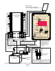
4.1.4 Review wiring diagram on page 3.
4.1.5 Can more than one charge controller be used?: If the TM-2030 and SC-2030 are connected together,
other charge controllers may be added for additional charging current, while still retaining most of the benefits gained
by using this paired system. They must be connected so the TM-2030 "sees" this current when they are charging. Also,
though all chargers go to the same battery set, the solar panels should be segregated into groups—with each group being
controlled by only one charger.
4.1.5 Locating TM-2030 monitor and SC-2030 charger. The TM-2030 is usually placed somewhere with
access in the living area to allow easy viewing and control of the SC-2030. Four small wires usually 22 or 24 gauge
connect the TM-2030 to the batteries and required shunt. In addition a four wire telephone cable will need to be
installed that sends control information from TM-2030 to SC-2030. These wires can be at least 100 feet long (30
meters). The SC-2030 will usually be located in the wire path from panels to batteries to minimize wire length from
panels to batteries. Unless the SC-2030 will be used without the TM-2030, it is not required that the SC-2030 be located
right near the batteries.
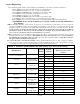
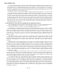
TABLE 1: Required minimum copper wire size for 3% loss.
One way total length from solar panels to SC-2030 plus SC-2030 to batteries
Length for 12V systems: For 24V systems double all distances
Maximum amps from
panels→
5 Amps
10 Amps
15 Amps
20 Amps
25 Amps
30 Amps
Wire
gauge
(AWG)
Diameter
(mm)
(ft)
(m)
(ft)
(m)
(ft)
(m)
(ft)
(m)
(ft)
(m)
(ft)
(m)
2*
6.544
230
70
115
35
76
23
57
17
46
14
38
11
4*
5.189
144
44
72
22
48
14
36
11
28
8
24
7
6
4.115
91
27
45
13
30
9
22
6
18
5
15
4
8
3.264
57
17
28
8
19
5
14
4
11
3
9
2
10
2.588
36
10
18
5
12
3
9
2
7
2
**
12
2.053
22
6
11
3
7
2
**
**
**
*This wire gauge exceeds the terminal block’s maximum wire size and requires adapting.
** Not recommended
4.1.6 Determine wire size required from solar panels to charger and batteries from Table 1 above.
Wire size from solar panels to SC-2030 and from SC-2030 to batteries must be much larger for low voltage systems
compared to 120V house wiring to minimize power loss. The required size depends on (1) total maximum amps to be
delivered by the panels, (2) the system volts (12 or 24), and (3) the wire length. The recommended maximum lengths
assume a 3% maximum power loss using copper wire in a 12V system. Doubling lengths will increase loss to 6%.
However for 24V system double all lengths for 3% loss. All wiring must meet applicable electrical code requirements
with respect to maximum current versus gauge. With less than 3% power loss, this is normally not a problem.