
TM-2030 Technical Manual

SHUNT: 50 MV/500 AMP
OR 100 MV/100 AMP
G1
G2
SIG
G1
G2
SIG
+
-
B2+
TM-2030
G1
G2
SIG
B2+
B1+
B1+
B1+
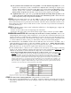
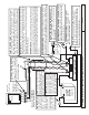
Back view of
battery monitor panel.
TriMetric
12 TO 48V
BATTERY
SYSTEM
Measure volts,
amps, % full.
OPTIONAL SECOND BATTERY:
B2+ may be connected (for
example) to the + terminal of a
starting battery so you can use the
meter to observe voltage.
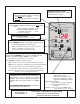
SHUNT TO METER CABLE (unshielded): Can be up to 300 ft. long if
cable has #18 or larger wires, or 100 feet using #22 wires. Twisted
pair is normally not necessary. However, if it is used, we recommend
wiring it as shown in the diagram. Use one twisted pair for the G1 and
+ wires, and another twisted pair for the G2 and SIG wires (as shown).
IMPORTANT NOTE:
maintained for accuracy.
TECHNICAL NOTE:
The two wires: G1, G2 must be connected to each other
ONLY right at the shunt terminal at the small screw (Kelvin connection) for
accurate current measurements. (Otherwise meter will show residual
"amps" when it should be showing zero.) Also, good connections must be
The reason the G1 and G2 wires must be connected together ONLY
at the shunt, is that to measure current through the battery the TriMetric measures voltages
across the shunt between the SIG and G2 wires as small as 10 microvolts. The voltage drop
across the G1 wire from the shunt to the meter (due to current flow through the wire) can easily be
100 millivolts. Only when the connections are made as shown, the G2 wire carries no current,
thus there is no error causing voltage drop across it. (1 volt=1000 millivolts = 1,000,000
microvolts.)
KELVIN CONNECTIONS: These are the two smaller screws on the shunt
which should be used for current sensing wires only. For measurement
accuracy, don’t connect wires containing high currents to these connections.
2nd BATTERY SYSTEM TO MEASURE VOLTS
ONLY: (if used) NEGATIVE side connects as shown
here, to this side of shunt, not directly to main battery
system negative.
SYSTEM GROUND ON THIS SIDE OF SHUNT (if used)
Minus terminal of charge controller, inverter, and all other
loads and chargers connect to this side of shunt (not the
negative post of battery).
T (SOLAR PANELS including
CONTROLLER, CHARGER, ALTERNATOR, ETC.)
AND ALL LOADS (INVERTER, ETC.)
O CHARGING SYSTEM
SHUNT NOTE: Use a 50 mv/500 amp shunt or 100 mv/100
amp shunt. Shunt must be connected to minus side of
battery. To read correct current and amp-hours, TriMetric
battery monitor must be programmed for correct shunt type
being used, as described in instructions.
FOR SAFETY: Place a
1 amp (fast blow) fuse
in series with the + wire
near the battery, as
shown. That way, if
there is ever a short
between this wire and
the other wires, you
won't melt down the
wires, you will only blow
the fuse. ALSO
protects the meter if
accidentally miswired.
IMPORTANT: Be sure this side of
shunt is connected to nothing but
negative terminal(s) of the battery
set that you want to monitor the
"amps". Otherwise your meter amps
will not be correct. (If 2nd battery is
used, with only volts measured,
connect as shown at right.)
NOTE: The SIG wire must be connected
to the small screw (kelvin connection) on
the shunt, not the larger bolt which
connects to the battery. If not, "amps"
measurements will be inaccurate.
Magnified view of
5 TERMINAL
STRIP located on
circuit board.
FIGURE 2: TM-2030 TriMetric Battery Monitor Connections
3/20/14
2nd Batt.
measure volts
only
To SC-2030
charger if used