
Bogart Engineering SC-2030 Technical Manual
Bogart Engineering
6 of 16
4.1.7 Install TM-2030 monitor if not already installed according to "Installer's instructions for
TM-2030"
4.2. Verifying that TM-2030 reads volts and amps correctly
Proper charging depends critically on accuracy of TM-2030 voltage and current (amps) readings.
Check volts: For accurate battery-voltage control, the TriMetric’s voltage-measurement wire (called “B1” in TriMetric
wiring diagram) must be connected directly, or close to the battery’s positive terminal.
Check amps on the AMPS TriMetric display:
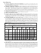
●Under zero-current conditions when all loads and charging sources are off, the TriMetric’s ampere indicator must show
0.0A, or ±0.1A at most when using the standard 500A/50mV shunt. When using the less common 100A/100mV shunt,
the zero-current value should be between minus 0.02-0.04A —which represents the current drawn by the TriMetric.
●The discharge current should be measured reasonably. For instance, a 12V, 12W light bulb connected to a 12V battery
should display approximately −1A. This assumes no charging is going on, since the amps display shows charge minus
discharge. The formula for Amps =Watts ÷ System Volts (12V or 24V).
●Verify that ALL charging sources should be shown as positive amps on the TriMetric TM-2030 when charging. All loads
on the batteries should show as negative values when they are operating. Related to this:
●The following is worth checking, because this mistake is so common: Check to make sure that nothing except battery
negative (no loads or charging sources or grounds) is connected to the battery negative side of the shunt—as illustrated in
figure 1 of the TM-2030 INSTALLATION INSTRUCTIONS.
4.3 Tools and hardware required
●Drill with bits of suitable sizes for entry of telephone cable and/or Temperature sensor into SC-2030 plastic enclosure
●Medium Phillips screwdriver for the large green terminal blocks connecting wire to panels and batteries.
●Small Phillips screwdriver for four screws holding front plate enclosure
●Wire cutters, wire strippers, and a lug crimper for the battery wire, the solar panel wire, etc.
●SC-2030 charge controller
●TM-2030 (TriMetric) battery monitor with sensing and power wires (assuming the TM-2030 will be connected)
●If TM-2030 is not yet installed, it will require an electrical shunt: 500A/50mV or 100A/100mV size. see TM-2030
installation instructions.
●Mounting hardware for the above, if required
●Wire of suitable size and length (as determined in section 4.1.6) from panels to SC-2030 and SC-2030 to batteries
● Common four wire conductor “telephone cable” up to 100 ft. long—to go from SC-2030 to TM-2030. This is the
common 4 wire telephone extension cable with RJ11 connectors sold in different lengths at hardware or other stores in
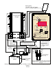
the telephone accessories section. The wiring must be crossed (crossover) between the two connectors, as shown in
the lower right-hand corner of Figure 1 on page 3. This is usually the way they are manufactured—but check.
●Temperature sensor (optional but recommended unless batteries will remain at same temperature)
4.4 Installing the SC-2030, connecting solar panels, batteries, and Temperature sensor
Plan to mount the SC-2030 in a well-ventilated and shaded area to prevent overheating, and protected from direct rainfall.
The heat sink can get hot during charging; therefore, the charge controller must be installed beyond the reach of animals and
young children. The black heat sink fins should be vertical—not horizontal, which means the printing of "SOLAR" or
"BATTERY" will be right side up or upside down (not sideways).
4.4.1 Run wires (size determined as described section 4.1.6) from solar panels to location for SC-2030, and from batteries
to SC-2030 location with enough extra length to easily connect to large green terminal blocks. Carefully mark on the
ends of the wire which are positive and which are negative—both to batteries and to solar panels.
4.4.2 If communication (phone) cable has RJ14 connectors attached at both ends, check that connectors are "crossed" as
shown in figure 1. Run phone cable from TM-2030 to SC-2030 location with sufficient length. If you have a RJ14
crimp tool and correct RJ14 connector, to avoid drilling a larger hole you could pass wire through a small drilled hole
through TM-2030 enclosure then use crimp tool to install connector (carefully observing polarity Fig 1). Don't yet
connect the communication cable to the TM-2030 (unless connectors at each end are attached and you don't intend to
put them on or change them later.)
4.4.3 Remove front panel and circuit board from SC-2030 enclosure by removing 4 screws and put it aside. Drill one or
more holes in the SC-2030 enclosure to allow the communication cable and the temperature sensor wire (if used) to
pass through in a location suitable to the positioning of the controller, wires and the rest of the system. The
temperature sense connector requires a 5/16 diameter hole to pass through. For the communication cable, as described
in 4.4.2 you could pass the wire through the hole and attach the connector similarly to 4.4.2 if you have the
appropriate connector and crimping tool. Reminder: be sure the connectors are attached "crossed" as shown figure 1.