™ Boekel InSlide Out Hybridization Oven Models 241000 and 241000-2 Operating Instructions N2400117 Rev.
CONTENTS 1. 2. 3. 3.1 3.2 4. 4.1 4.2 4.3 4.4 4.5 5. 5.1 6. 7. 8. 8.1 8.2 9. 10. Page Safety .............................................................................................................................. 2 Product Information ........................................................................................................ 3 Assembly......................................................................................................................... 3 Unpacking .....................
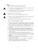
1. Safety The following symbols marked on the equipment mean: Caution: Read these operating instructions fully before use and pay particular attention to sections containing this symbol. Attention: Suivre attentivement les instructions avant l’usage et prêtez une attention particulière aux sections comportant ce symbole. Caution: Surfaces can become hot during use. Attention: Les surfaces peuvent devenir brûlantes pendent l’usage. Caution: Risk of electric shock.
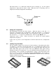
2. Product Information The InSlide Out Hybridization Oven is designed so its sealed tray maintains a humid condition for In-Situ Hybridization applications without the need to use sealed cover slips. Uses include in-situ RNA amplification, reverse transcription reactions and hybridizations, and immunohistochemical reactions. The InSlide Out can hold up to twenty standard microscope slides on the standard wire rack. An optional slide holder can hold up to eighteen standard microscope slides.
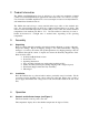
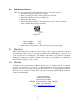
The heater lamp is on continuously while the Oven is heating up. As the required temperature is approached, it starts to flash. When the unit is controlling at the set temperature, the heater lamp flashes intermittently. Heater Lamp Temperature Display * Figure 1 4.2 Setting the Temperature The Temperature Controller has three buttons. When the button on the left ‘*’ is depressed, it will display the set temperature.
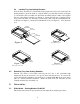
4.4 Loading Tray into Heating Chamber Once the Tray Assembly is loaded and the slides prepared, the tray can be loaded into the heating chamber. Open the main door, lift the frame, pivot the latch forward (see Figure 5), and slide the Tray Assembly into the Frame Assembly until it is fully seated against the rear of the Frame Assembly (see Figure 6). Rotate the latch into a vertical position and position the latch over the keeper on the frame, then rotate the Latch Handle ˚180 clockwise (see Figure 7).
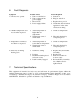
6. Fault Diagnosis Symptom 1. Unit does not operate 2. Chamber temperature does not rise when expected 3. Temperature continues to rise when not expected 4. Slides dry out during heating cycle Possible Cause a. Unit not switched on b. Unit not plugged into power supply c. Fuses blown d. Power supply failure Action Required a. Switch on b. Plug in, switch on a. Actual temperature is higher than set temperature b. Temperature control circuit fault a. Check set temperature a.
Specifications: Temperature Range: Setting Range: Stability: Overall Accuracy: Temperature Display Resolution: Supply Voltage Range: Power Rating: Heating Rate: 8. (Ambient +10°C) to 75°C 0°C to 75°C +/- 0.2°C +/- 0.5°C at 65°C 0.1°C 115V +/- 10%, 1.35A, 60 Hz 230V +/- 10%, 0.67A, 50/60 Hz Model 241000: 155W Model 241000-2: 155W Ambient to 50°C within 20 minutes Maintenance and Service All Boekel laboratory products are designed to comply with IEC1010-1. maintenance is required. 8.
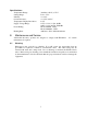
8.2 Replacement of Fuses There are two supply fuses located in the fuse drawer. To replace the fuses: • Disconnect the unit from the power supply. • Remove the plug from the socket in the back of the unit. • Pull back on the fuse drawer (see Figure 11). • Pull out the fuse drawer. • Check and replace with the correct fuses if necessary. The fuses must be 5mm x 20mm quick acting, rated 250V. Fuse Drawer Figure 11 • 9. Model 241000: -2AF Model 241000-2: -1AF Push the fuse drawer back in.