Smootharc MMA 170 O P E R AT I N G M A N U A L
Welcome to a better way of welding Congratulations on puchasing the Smootharc MMA 170 welding machine. The products in BOC's manual metal arc range perform with reliability and have the backing of one of South Pacific's leading welding suppliers. This operating manual provides the basic knowledge required for MMA and DC TIG welding, as well as highlighting important areas of how to operate the Smootharc MMA 170 welding machine.
Contents Welcome to a better way of welding 2 4.0 Machine Specifications and Contents 28 1.0 Recommended Safety Precautions 4 4.1 28 1.1 Health Hazard Information 4 5.0 Operating Functions 29 1.2 Personal Protection 4 5.1 Welding selections 29 1.3 Electrical Shock 6 5.2 Earthing 29 1.4 User Responsibility 6 Operating Controls 6.0 Technical Specifications 30 7.0 Periodic Maintenance 31 7.1 Daily Maintenance 31 Troubleshooting 31 2.
1.0 Recommended Safety Precautions 1.1 Health Hazard Information The actual process of welding is one that can cause a variety of hazards. All appropriate safety equipment should be worn at all times, i.e. headwear, respiratory, hand and body protection. Electrical equipment should be used in accordance with the manufacturer’s recommendations. Eyes: The process produces ultra violet rays that can injure and cause permanent damage. Fumes can cause irritation. Skin: Arc rays are dangerous to uncovered skin.
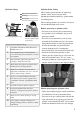
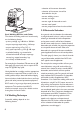
Cylinder Safety Cylinder Valve Safety 1 Cylinder valve hand-wheel 2 Back-plug 3 Bursting disc When moving cylinders, ensure that the valve is not accidentally opened in transit. 1 Before operating a cylinder valve: 2 3 Backview of typical cylinder valve Operator wearing personal protective equipment (PPE) in safe position Ten Points about Cylinder Safety 1 Read labels and Material Safety Data Sheet (MSDS) before use.
the valve. Approved leak detection fluid, can be obtained from a BOC Gas & Gear™centre. • Always disconnect mains power before investigating equipment malfunctions. • When finished with the cylinder, close the cylinder valve by hand by turning the valve hand-wheel in a clockwise direction. Use only reasonable force. • Parts that are broken, damaged, missing or worn should be replaced immediately. • Equipment should be cleaned periodically. Remember NEVER tamper with the valve.
2.0 Manual Metal Arc Welding Process (MMAW) 2.1 Introduction Arc welding, although in the past principally the tool of tradesmen and fabricators, has in recent years found increasing usage with small workshops, farmers, handyman-hobbyists amongst others. This has been brought about by the introduction of low-cost portable arc welding machines and the ready availability of small diameter electrodes and thinner section construction materials.
• selection of the correct electrode Lift-TIG • selection of the correct size of the electrode for the job • correct welding current • correct arc length • correct angle of electrode to work • correct travel speed • correct preparation of work to be welded. 2.5 Electrode Selection Basic Welding Machine and Cables The choice of welding machine is based mostly on the following factors: • primary voltage, e.g. 240 Volt or 380 Volt • output amperage required, e.g. 140 amps • output required, e.g.
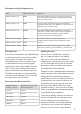
Electrodes and Typical Applications Name AWS Classification Application BOC Smootharc 13 E6013 A premium quality electrode for general structural and sheet metal work in all positions including vertical down using low carbon steels BOC Smootharc 24 E7024 An iron powder electrode for high speed welding for H-V fillets and flat butt joints.
The limits of this range should not normally be exceeded. The following table shows the current ranges generally recommended for BOC Smootharc 13. Generally Recommended Current Range for BOC Smootharc 13 Size of Electrode (mm) Current Range (Amp) 2.5 60–95 3.2 110–130 4.0 140–165 5.0 170–260 Arc Length To start the arc, the electrode should be gently scraped on the work until the arc is established.
2.6 Types of Joints Double ‘V’ Butt Weld Used on plate of 12 mm and over in thickness when welding can be applied from both sides. It allows faster welding and greater economy of electrodes than a single ‘V’ preparation on the same thickness of steel and also has less of a tendency to distortion as weld contraction can be equalised. Butt Welds A butt weld is a weld made between two plates so as to give continuity of section.
General notes on Butt Welds LAYERS Electrode Angle for Subsequent Layers The first run in a prepared butt weld should be deposited with an electrode not larger than 4.0 mm. The angle of the electrode for the various runs in a butt weld is shown. It is necessary to maintain the root gap by tacking at intervals or by other means, as it will tend to close during welding.
‘T’ Joints A fillet weld may be placed either on one or both sides, depending on the requirements of the work. The weld metal should fuse into or penetrate the corner formed between the two members. Where possible the joint should be placed in such a position as to form a “Natural ‘V’ fillet” since this is the easiest and fastest method of fillet welding.
Concave Fillet Weld A fillet in which the contour of the weld is below a straight line joining the toes of the weld. It should be noted that a concave fillet weld of a specified leg length has a throat thickness less than the effective throat thickness for that size fillet. This means that when a concave fillet weld is used, the throat thickness must not be less than the effective measurement. This entails an increase in leg length beyond the specified measurement.
Multi-run horizontal fillets have each run made using the same run lengths (run length per electrode table). Each run is made in the same direction, and care should be taken with the shape of each, so that it has equal leg lengths and the contour of the completed fillet weld is slightly convex with no hollows in the face. Vertical fillet welds can be carried out using the upwards or downwards technique.
Slag inclusions occur when slag particles are trapped inside the weld metal which produces a weaker weld. These can be caused by: • erratic travel speed • too wide a weaving motion • slag left on the previous weld pass type and size of electrode and the welding position • holding the arc as short as possible • pausing at each side of the weld bead when a weaving technique is used • letting slag run ahead of the arc.
3.0 Gas Tungsten Arc Welding (GTAW/TIG) 3.1 Introduction The Tungsten Inert Gas, or TIG process, uses the heat generated by an electric arc struck between a non-consumable tungsten electrode and the workpiece to fuse metal in the joint area and produce a molten weld pool. The arc area is shrouded in an inert or reducing gas shield to protect the weld pool and the non-consumable electrode.
Lift Arc™ During this method of arc initiation, the tungsten is actually touching the workpiece. This occurs at very low amperage that is only sufficient to pre-heat, not melt the tungsten. As the tungsten is moved off the plate, the arc is established. With this method, there is little chance of tungsten inclusion occurring. 3.
3.4 Welding Techniques Welding techniques Vertical Welding Rod 60–75° Shield gas Nozzle 15–30° Tungsten electrode Direction of travel The suggested electrode and welding rod angles for welding a bead on plate. The same angles are used when making a butt weld. The torch is held 60–75° from the metal surface. This is the same as holding the torch 15–30° from the vertical. Take special note that the rod is in the shielding gas during the welding process.
3.5 Shielding Gas Selection Brass With argon, the arc is stable and there is little smoke. Cobalt-based alloys Argon provides a stable, easy-to-control arc. Copper nickel (Monel) Argon gives a stable, easy-to-control arc. Also used for welding copper nickel to steel. Deoxidised copper Helium is preferred as it helps greatly in counteracting thermal conductivity of copper. A mixture of 75% helium and 25% argon (Alushield Heavy) produces a stable arc, less heat than an arc produced with helium alone.
3.6 Consumable Selection a) Welding wire The following table includes the recommended welding consumable for the most commonly welded materials. Base Material BOC Consumable C-Mn and low Carbon steels BOC Mild steel TIG wire Low Alloy steels 1.25Cr/0.5Mo Comweld CrMo1 2.5Cr/1Mo Comweld CrMo2 Stainless Steel 304/304L Profill 308 316/316L Profill 316 309/309-C-Mn Profill 309 321/Stabilised grades Profill 347 Filler rod diameter (mm) Thickness of metal (mm) 2 0.
b) Non consumable Tungstens Tungsten Electrode Selector Chart Base metal type Thickness range Desired results Welding current Electrode type Copper alloys, Cu-NI alloys and Nickel alloys All General purpose DCSP 2% Thoriated (EW-Th2) 2% Ceriated (EW-Ce2) Mild Steels, Carbon Steels, Alloy Steels, Stainless Steels and Titanium alloys Only thin sections Control penetration ACHF Zirconiated (EW-Zr) Only thick sections Increase penetration or travel speed DCSP 2% Ceriated (EW-Ce2) All Genera
Shielding gas Tungsten performance characteristics 75% Argon/ 25% Helium Best stability at medium currents. Good arc starts. Medium tendency to spit. Medium erosion rate. 75% Argon/ 25% Helium Low erosion rate. Wide current range. AC or DC. No spitting. Consistent arc starts. Good stability. Argon Use on lower currents only. Spitting on starts. Rapid erosion rates at higher currents. 75% Argon/ 25% Helium Low erosion rate. Wide current range. AC or DC. No spitting. Consistent arc starts.
Tungsten tip preparation Tungsten Grinding Shape by grinding longitudinally (never radially). Remove the sharp point to leave a truncated point with a flat spot. Diameter of flat spot determines amperage capacity. (See below) DCSP (EN) or DCRP (EP) = Diameter Flat 1/4–1/2x Dia Taper length 2–3x Dia The included angle determines weld bead shape and size. Generally, as the included angle increases, penetration increases and bead width decreases. ACHP General Purpose Max.
3.7 Typical Welding Joints for Gas Tungsten Arc Welding Butt welds TIG welding is commonly combined with other faster filling processes such as MMA or MIG welding. It is therefore not uncommon to use the same weld preparations as would have been used for the filling process. When welding a butt joint, centre the weld pool on the adjoining edges. When finishing, decrease the heat (amperage) to aid in filling the crater.
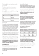
Troubleshooting guide Problem Cause Excessive 1. Inadequate gas flow electrode 2. Improper size electrode for consumption current required 3. Operating of reverse polarity 4. Electrode contamination 5. Excessive heating inside torch 6. Electrode oxidising during cooling 7. Shield gas incorrect 1. Increase gas flow 2. Use larger electrode Erratic Arc 1. Incorrect voltage (arc too long) 2. Current too low for electrode size 3. Electrode contaminated 4. Joint too narrow 5. Contaminated shield gas.
Troubleshooting guide Problem Cause Solution Porosity in Weld Deposit 5. Alloy impurities in the base metal such as sulphur, phosphorous, lead and zinc 6. Excessive travel speed with rapid freezing of weld trapping gases before they escape 7. Contaminated shield gas 5. Change to a different alloy composition which is weldable.These impurities can cause a tendency to crack when hot. 6. Lower the travel speed 1. Hot cracking in heavy section or with metals which are hot shorts 1. Preheat.
4.0 Machine Specifications and Contents 4.
5.0 Operating Functions 5.1 Welding selections 1 2 Manual Metal Arc welding (MMA) ■■ Lift-TIG 3 4 5 ■■ ■■ Select the current as per the recommendations of the consumable manufacturer. Select the polarity of the electrode cable as per the recommendations (+/-) Select the process selector switch to MMA 1 Power indicator light 2 Overtemperature control indicator 3 Welding current regulator 4 On/Off switch 5 Process selector switch MMA/Lift TIG Always switch the machine off at the supply switch.
6.0 Technical Specifications MMA170 Part No. MMA170P Input Voltage (V) 1PH AC240V±15% Frequency (Hz) 50/60 Input Plug Requirement Industrial Heavy duty 15A Rated Current (A) MMA 27.5 TIG 20.3 No-load Voltage (V) 65 Output Current Range (A) 20-170 Rated Output Voltage (V) 26.8 16.8 Duty Cycle (%) 35% 100% 170A 132A 170A 132A MMA TIG No-load Loss (W) 40 Efficiency (%) 80 Power Factor 0.73 Insulation Grade F Housing Protection Grade IP21 Weight (kg) 7.
7.0 Periodic Maintenance In maintenance of the unit, take into consideration the rate of use and the environment it is used in. When the unit is used properly and serviced regularly, you will avoid unnecessary disturbances in use and production. 7.1 Daily Maintenance • Check that there is ample space in front of and back of the unit for ventilation. • Check welding settings. See 5.
8.0 Terms of Warranty Warranty for Smootharc MMA170 8.3 Warranty Repairs 8.1 Terms of Warranty BOC or their Authorised Service Agent must be informed of the warranty defects, and the product returned within the warranty period. BOC provides a warranty for the Smootharc MMA170 sold by it against defects in manufacture and materials. • Valid for 18 months from date of purchase. • An authorised BOC Service Agent must carry out warranty repairs.
9.0 Recommended Safety Guidelines Some safety precautions BOC recommends are as follows: • Repair or replace defective cables immediately. • Never watch the arc except through lenses of the correct shade. • In confined spaces, adequate ventilation and constant observation are essential. • Leads and cables should be kept clear of passageways. • Keep fire extinguishing equipment at a handy location in the shop. • Keep primary terminals and live parts effectively covered.
34
35
For more information on any BOC product or service call the BOC Customer Service Centre on: AU S TRA L I A 131 262 Email: contact@boc.com Website: www.boc.com.au NEW Z EA L AN D 0800 111 333 Email: customer-service-nz@boc.com Website: www.boc.co.